Subaru Crosstrek Service Manual: Dtc c0052 motor malfunction
VEHICLE DYNAMICS CONTROL (VDC) (DIAGNOSTICS) > Diagnostic Procedure with Diagnostic Trouble Code (DTC)
DTC C0052 MOTOR MALFUNCTION
DTC detecting condition:
• Defective motor and motor relay
• Defective harness connector
Trouble symptom:
• ABS does not operate.
• VDC does not operate.
• EBD may not operate.
• EyeSight does not operate.
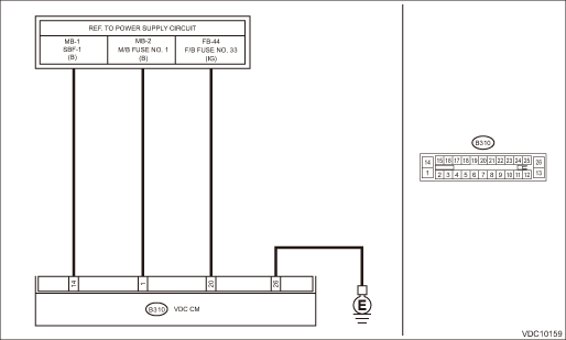
Wiring diagram:
Vehicle dynamics control system Vehicle Dynamics Control System > WIRING DIAGRAM">
| STEP | CHECK | YES | NO |
1.CHECK VDCCM&H/U INPUT VOLTAGE.
1) Turn the ignition switch to OFF.
2) Disconnect the connector from the VDCCM&H/U.
3) Turn the ignition switch to ON.
4) Measure the voltage between VDCCM&H/U connector and chassis ground.
Connector & terminal
(B310) No. 14 (+) — Chassis ground (−):
(B310) No. 20 (+) — Chassis ground (−):
Is the voltage 10 — 15 V?
Diagnostic Procedure with Diagnostic Trouble Code (DTC) > DTC C0052 MOTOR MALFUNCTION">Go to Step 2.
Repair the VDCCM&H/U power supply circuit.
2.CHECK VDCCM&H/U INPUT VOLTAGE.
Calculate the voltage difference measured in step 1.
A: (B310) No. 14 (+) — Chassis ground (−):
B: (B310) No. 20 (+) — Chassis ground (−):
Is the voltage difference between A and B 2 V or more?
Repair the power supply circuit.
Diagnostic Procedure with Diagnostic Trouble Code (DTC) > DTC C0052 MOTOR MALFUNCTION">Go to Step 3.
3.CHECK INSTALLATION OF VDCCM&H/U GROUND.
Is the VDCCM&H/U ground terminal installation bolt (ground bolt fixing onto the side frame upper face) installed correctly?
Diagnostic Procedure with Diagnostic Trouble Code (DTC) > DTC C0052 MOTOR MALFUNCTION">Go to Step 4.
Install the VDCCM&H/U ground terminal installation bolt correctly.
4.CHECK VDCCM&H/U GROUND CIRCUIT (CHECK FOR OPEN CIRCUIT).
1) Turn the ignition switch to OFF.
2) Measure the resistance between VDCCM&H/U connector and chassis ground.
Connector & terminal
(B310) No. 26 — Chassis ground:
Is the resistance less than 10 ??
Diagnostic Procedure with Diagnostic Trouble Code (DTC) > DTC C0052 MOTOR MALFUNCTION">Go to Step 5.
Repair the VDCCM&H/U ground harness.
5.CHECK VDCCM&H/U MOTOR RELAY.
Measure the resistance between VDCCM&H/U terminals.
Connector & terminal
No. 14 — No. 26:
Is the resistance 1 M? or more?
Diagnostic Procedure with Diagnostic Trouble Code (DTC) > DTC C0052 MOTOR MALFUNCTION">Go to Step 6.
Replace the VDCCM&H/U. VDC Control Module and Hydraulic Control Unit (VDCCM&H/U)">
6.CHECK POOR CONTACT OF CONNECTORS.
Turn the ignition switch to OFF.
Is there poor contact of connector between generator, battery and VDCCM&H/U?
Repair the connector.
Diagnostic Procedure with Diagnostic Trouble Code (DTC) > DTC C0052 MOTOR MALFUNCTION">Go to Step 7.
7.CHECK VDCCM&H/U.
1) Connect all connectors.
2) Perform the Clear Memory Mode. Clear Memory Mode">
3) Perform the Inspection Mode. Inspection Mode">
4) Read the DTC. Read Diagnostic Trouble Code (DTC)">
Is the same DTC displayed?
Replace the VDCCM&H/U. VDC Control Module and Hydraulic Control Unit (VDCCM&H/U)">
Diagnostic Procedure with Diagnostic Trouble Code (DTC) > DTC C0052 MOTOR MALFUNCTION">Go to Step 8.
8.CHECK DETECTION OF OTHER DTCS FOR VDC.
Read Diagnostic Trouble Code (DTC)">
Is any other DTC displayed?
Perform the diagnosis according to DTC. List of Diagnostic Trouble Code (DTC)">
Currently, it is normal. There may have been a temporary poor contact in the harness and connector or a temporary noise interference.
 Dtc c0051 valve relay
VEHICLE DYNAMICS CONTROL (VDC) (DIAGNOSTICS) > Diagnostic Procedure with Diagnostic Trouble Code (DTC)DTC C0051 VALVE RELAYDTC detecting condition:Defective valve relayTrouble symptom:• ABS d ...
 Dtc c0054 bls on malfunction
VEHICLE DYNAMICS CONTROL (VDC) (DIAGNOSTICS) > Diagnostic Procedure with Diagnostic Trouble Code (DTC)DTC C0054 BLS ON MALFUNCTIONDTC detecting condition:Defective stop light switchTrouble symptom: ...
Other materials:
Dtc u0140 lost communication with body control module
AUTO HEADLIGHT BEAM LEVELER SYSTEM (DIAGNOSTICS) > Diagnostic Procedure with Diagnostic Trouble Code (DTC)DTC U0140 LOST COMMUNICATION WITH BODY CONTROL MODULEDetected when CAN data (headlights ON signal) is not received from the body integrated unit.NOTE:Perform the diagnosis for LAN system. Ba ...
Function settings
A SUBARU dealer can change the settings of the functions shown in the
following table to meet your personal requirements. Contact
the nearest SUBARU dealer for details. If your vehicle is equipped with a multi
function display, the settings for some of these functions
can be changed using the ...
Procedure
LAN SYSTEM (DIAGNOSTICS) > CAN Communication Circuit CheckPROCEDURENOTE:• When measuring the resistance of CAN communication circuit, measure it in sleep status.To enter sleep status– With ignition switch OFF and key or switch operation stopped, keep the doors, trunk, and rear gate all c ...
