Subaru Crosstrek Service Manual: Procedure
LAN SYSTEM (DIAGNOSTICS) > CAN Communication Circuit Check
PROCEDURE
NOTE:
• When measuring the resistance of CAN communication circuit, measure it in sleep status.
To enter sleep status
– With ignition switch OFF and key or switch operation stopped, keep the doors, trunk, and rear gate all closed for one minute or more.
– On models with keyless access function, keep the access key 2 m or more away from the vehicle.
• When the bus line is measured, combined resistance of the end resistance (120 ?) in ECM and the end resistance (120 ?) in VDC CM can be measured. The combined resistance is supposed to be approximately 53 — 61 ? with the stabilizing circuit included. If the measured resistance value becomes 52 ? or less, main wiring harness or related lines may be shorted. Or, the combined resistance may have changed because of a resistance other than the end resistance created on the circuit. If the measured value is 62 ? or more, there may be a malfunction such as open circuit in one of the end resistances, in the stabilizing circuit, or in the main wiring harness.
Also, even when the resistance value falls within approx. 53 — 61 ?, related lines may be open if an error of communication for initializing or a CAN system U-code has occurred. (The resistance cannot be between approx. 53 — 61 ? if the main wiring harness is open.)
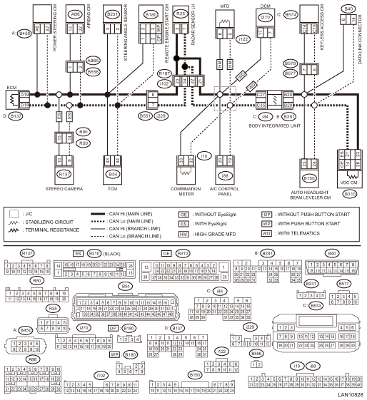
Wiring diagram:
CAN communication system CAN Communication System > WIRING DIAGRAM">
• Without BSD/RCTA
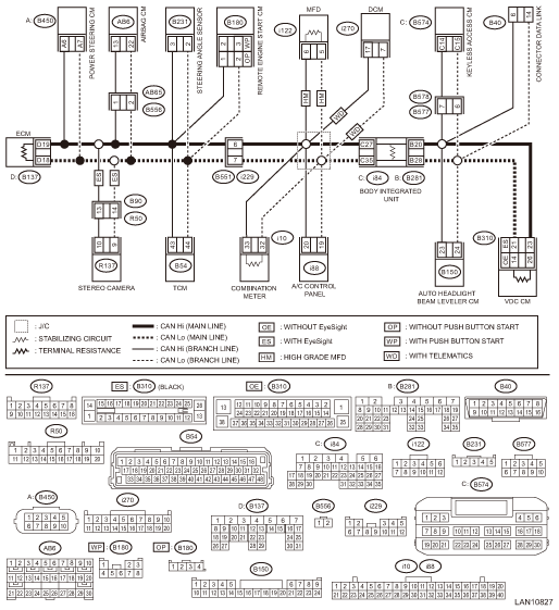
• With BSD/RCTA
| STEP | CHECK | YES | NO |
1.CHECK BASIC DIAGNOSTIC PROCEDURE.
Check that the basic diagnosis has been performed up to STEP 3.
NOTE:
Possible defective parts can be narrowed easily by inspection using Subaru Select Monitor before performing “CHECK CAN COMMUNICATION CIRCUIT” using a tester.
Was the basic diagnostic procedure performed?
CAN Communication Circuit Check > PROCEDURE">Go to Step 2.
Perform the basic diagnostic procedure. Basic Diagnostic Procedure > PROCEDURE">
2.CHECK FROM DATA LINK CONNECTOR.
Using the tester, measure the resistance between terminals.
Connector & terminal
(B40) No. 6 — Chassis ground:
(B40) No. 14 — Chassis ground:
Is the resistance less than 10 ??
Check for ground short. CAN Communication Circuit Check > INSPECTION">
CAN Communication Circuit Check > PROCEDURE">Go to Step 3.
3.CHECK FROM DATA LINK CONNECTOR.
1) Turn the ignition switch to ON.
2) Using the tester, measure the voltage between terminals.
Connector & terminal
(B40) No. 6 — Chassis ground:
(B40) No. 14 — Chassis ground:
Is the voltage 5 V or less?
CAN Communication Circuit Check > PROCEDURE">Go to Step 4.
Check for battery short. CAN Communication Circuit Check > INSPECTION">
4.CHECK FROM DATA LINK CONNECTOR.
1) Turn the ignition switch to OFF.
2) Using the tester, measure the resistance between terminals.
Connector & terminal
(B40) No. 6 — No. 14:
Is the resistance 52 ? or less?
Perform the inspection for resistance of 52 ? or less. CAN Communication Circuit Check > INSPECTION">
CAN Communication Circuit Check > PROCEDURE">Go to Step 5.
5.CHECK FROM DATA LINK CONNECTOR.
Using the tester, measure the resistance between terminals.
Connector & terminal
(B40) No. 6 — No. 14:
Is the resistance 62 ? or more?
Perform the inspection for resistance of 62 ? or more. CAN Communication Circuit Check > INSPECTION">
If the display of CAN system U-code disappears from the current malfunction, the CAN network is currently normal. If the U-code has detected as current malfunction, related lines may be open. Perform the inspection for the related line corresponding to the detected DTC. CAN Communication Circuit Check > LIST">
 Inspection
LAN SYSTEM (DIAGNOSTICS) > CAN Communication Circuit CheckINSPECTION1. GROUND SHORT INSPECTIONWiring diagram:CAN communication system CAN Communication System > WIRING DIAGRAM">• ...

Other materials:
Installation
SECURITY AND LOCKS > Front Outer HandleINSTALLATION1. Before installation, check the following items.• Rod is free from deformation.• Grease is applied sufficiently to rod joints.If grease is insufficient, add it as necessary before assembling the rod.• If the lever is faulty, r ...
Door unlock selection function
The door unlock selection function makes
the following operations possible.
Unlocking the driver's door without
unlocking any other doors (including the
rear gate) when gripping the driver's door
handle
Opening the rear gate without unlocking
any doors when pressing the rear gate
op ...
Inspection
VEHICLE DYNAMICS CONTROL (VDC) (DIAGNOSTICS) > Warning Light Illumination PatternINSPECTION(1)Ignition switch(6)Light OFF(11)2 seconds or more(2)OFF(7)Light ON(12)Brake warning light (EBD warning light)(3)ON(8)2 seconds(13)Parking brake(4)Engine start(9)VDC OFF indicator light(14)Released(5)ABS w ...
