Subaru Crosstrek Service Manual: Dtc c0051 valve relay
VEHICLE DYNAMICS CONTROL (VDC) (DIAGNOSTICS) > Diagnostic Procedure with Diagnostic Trouble Code (DTC)
DTC C0051 VALVE RELAY
DTC detecting condition:
Defective valve relay
Trouble symptom:
• ABS does not operate.
• EBD does not operate.
• VDC does not operate.
• EyeSight does not operate.
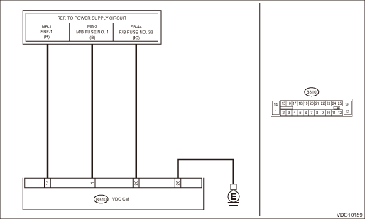
Wiring diagram:
Vehicle dynamics control system Vehicle Dynamics Control System > WIRING DIAGRAM">
| STEP | CHECK | YES | NO |
1.CHECK VDCCM&H/U INPUT VOLTAGE.
1) Turn the ignition switch to OFF.
2) Disconnect the connector from the VDCCM&H/U.
3) Run the engine at idle.
4) Measure the voltage between VDCCM&H/U connector and chassis ground.
Connector & terminal
(B310) No. 1 (+) — Chassis ground (−):
(B310) No. 20 (+) — Chassis ground (−):
Is the voltage 10 — 15 V?
Diagnostic Procedure with Diagnostic Trouble Code (DTC) > DTC C0051 VALVE RELAY">Go to Step 2.
Repair the power supply circuit.
2.CHECK VDCCM&H/U INPUT VOLTAGE.
Calculate the voltage difference measured in step 1.
A: (B310) No. 1 (+) — Chassis ground (−):
B: (B310) No. 20 (+) — Chassis ground (−):
Is the voltage difference between A and B 2 V or more?
Repair the power supply circuit.
Diagnostic Procedure with Diagnostic Trouble Code (DTC) > DTC C0051 VALVE RELAY">Go to Step 3.
3.CHECK INSTALLATION OF VDCCM&H/U GROUND.
Is the VDCCM&H/U ground terminal installation bolt (ground bolt fixing onto the side frame upper face) installed correctly?
Diagnostic Procedure with Diagnostic Trouble Code (DTC) > DTC C0051 VALVE RELAY">Go to Step 4.
Install the VDCCM&H/U ground terminal installation bolt correctly.
4.CHECK VDCCM&H/U GROUND CIRCUIT (CHECK FOR OPEN CIRCUIT).
1) Turn the ignition switch to OFF.
2) Measure the resistance between VDCCM&H/U connector and chassis ground.
Connector & terminal
(B310) No. 26 — Chassis ground:
Is the resistance less than 10 ??
Diagnostic Procedure with Diagnostic Trouble Code (DTC) > DTC C0051 VALVE RELAY">Go to Step 5.
Repair the VDCCM&H/U ground harness.
5.CHECK VDCCM&H/U VALVE RELAY.
Measure the resistance between VDCCM&H/U terminals.
Connector & terminal
No. 1 — No. 26:
Is the resistance 1 M? or more?
Diagnostic Procedure with Diagnostic Trouble Code (DTC) > DTC C0051 VALVE RELAY">Go to Step 6.
Replace the VDCCM&H/U. VDC Control Module and Hydraulic Control Unit (VDCCM&H/U)">
6.CHECK POOR CONTACT OF CONNECTORS.
Is there poor contact of connector between generator, battery and VDCCM&H/U?
Repair the connector.
Diagnostic Procedure with Diagnostic Trouble Code (DTC) > DTC C0051 VALVE RELAY">Go to Step 7.
7.CHECK VDCCM&H/U.
1) Connect all connectors.
2) Perform the Clear Memory Mode. Clear Memory Mode">
3) Perform the Inspection Mode. Inspection Mode">
4) Read the DTC. Read Diagnostic Trouble Code (DTC)">
Is the same DTC displayed?
Replace the VDCCM&H/U. VDC Control Module and Hydraulic Control Unit (VDCCM&H/U)">
Diagnostic Procedure with Diagnostic Trouble Code (DTC) > DTC C0051 VALVE RELAY">Go to Step 8.
8.CHECK DETECTION OF OTHER DTCS FOR VDC.
Read Diagnostic Trouble Code (DTC)">
Is any other DTC displayed?
Perform the diagnosis according to DTC. List of Diagnostic Trouble Code (DTC)">
Currently, it is normal. There may have been a temporary poor contact in the harness and connector or a temporary noise interference.
 Dtc c0045 tcm malfunction
VEHICLE DYNAMICS CONTROL (VDC) (DIAGNOSTICS) > Diagnostic Procedure with Diagnostic Trouble Code (DTC)DTC C0045 TCM MALFUNCTIONDTC detecting condition:Defective TCMTrouble symptom:• ABS does ...
 Dtc c0052 motor malfunction
VEHICLE DYNAMICS CONTROL (VDC) (DIAGNOSTICS) > Diagnostic Procedure with Diagnostic Trouble Code (DTC)DTC C0052 MOTOR MALFUNCTIONDTC detecting condition:• Defective motor and motor relay&bull ...
Other materials:
Basic screens
By operating the "
" or "
" switch on the
steering wheel, you can change the
screen that is always displayed.
Default screen
Digital speedometer
Menu screen entering screen
While this screen is selected, pull the "
/
SET" switch to enter the menu screen. ...
Inspection
MANUAL TRANSMISSION AND DIFFERENTIAL(5MT) > Reverse Check SleeveINSPECTION• Make sure the cutout of the reverse accent shaft is aligned with the opening in the reverse check sleeve.• Turn the cam by hand to check for smooth rotation.• Move the cam and shaft all the way toward th ...
Adjustment
EXTERIOR BODY PANELS > Rear GateADJUSTMENTAdjust the clearance around the panel - rear gate as follows.PartStandardAPanel - rear gate to Roof panel6.0+1.0, −0.5 mm (0.24+0.04, −0.02 in)BSurface level gap: Panel - rear gate to Roof panel1.0±1.0 mm (0.04±0.04 in)CPanel - rear gate to ...
