Subaru Crosstrek Service Manual: Suspension Inspection
PERIODIC MAINTENANCE SERVICES > Suspension
INSPECTION
1. FRONT SUSPENSION BALL JOINT
1. Lift up the vehicle until front wheels are off ground.
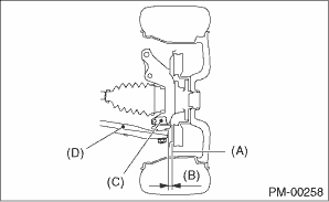
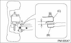
2. Grasp the bottom of tire and move it in and out in axial direction. If movement (B) is observed between the brake disc cover (A) and end of front arm (D), ball joint (C) may be excessively worn.
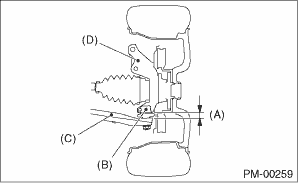
3. Next, grasp the end of front arm (C) and move it up and down. If movement (A) between the housing (D) and front arm (C) boss is observed, ball joint (B) may be excessively worn.
4. If the relative movement is observed in the preceding two steps, remove and inspect the ball joint. If the free play exceeds standard value, replace the ball joint. Front Ball Joint">
5. Damage of dust boot
Visually inspect the ball joint dust boot. Replace if ball joint is damaged.
NOTE:
When the front arm ball joint is removed or replaced, check the toe-in of front wheel. If it is not within the specified value, adjust the toe-in. Wheel Alignment">
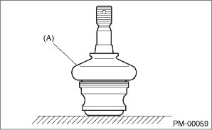
(A) | Dust boot |
2. REAR SUSPENSION BALL JOINT
1. Lift up the vehicle until rear wheels are off ground.
2. Grasp the bottom of tire and move it in and out in axial direction.
3. If movement is observed between the brake disc cover (A) and end of front lateral link (B), ball joint may be excessively worn.
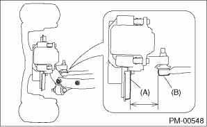
4. Grasp the end of front lateral link (B) and move it up and down. If movement is observed between the housing (C) and front lateral link (B) boss, ball joint may be excessively worn.
5. If the movement related to the previous two steps is observed, replace the front lateral link. Front Lateral Link">
6. Damage of dust boots
Visually inspect the ball joint dust boots. Replace if front lateral link is damaged.
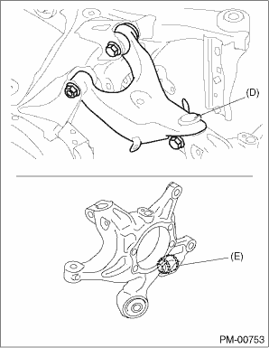
7. Check the upper arm ball joint (D) and the pillow ball bushing (E) of housing in the same manner.
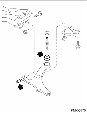
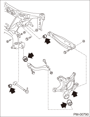
3. FRONT, REAR SUSPENSION BUSHING
Apply pressure with tire lever etc, and inspect the bushing for excessive wear or damage. If defective, replace the bushing.
• Front suspension bushing
• Rear suspension bushing
4. WHEEL ARCH HEIGHT
Refer to “FS” section for wheel arch height inspection. Wheel Alignment > INSPECTION">
5. WHEEL ALIGNMENT
Measure and adjust the front and rear wheel alignment at a time. Refer to “FS” section for measurement and adjustment of wheel alignment. Wheel Alignment > INSPECTION">
6. OIL LEAKAGE OF STRUT AND SHOCK ABSORBER
Visually inspect the front strut and rear shock absorber for oil leakage. Replace the front strut and rear shock absorber if oil leaks excessively.
7. TIGHTNESS OF BOLTS AND NUTS
Check the bolts and nuts for looseness. Retighten the bolts and nuts to specified torque. If the self-locking nuts and bolts are removed, replace them with new parts. General Description"> General Description">
8. DAMAGE TO SUSPENSION PARTS
Check the following parts and the fastening portion of the vehicle body for deformation or excessive rusting which impairs the suspension. Thoroughly remove the deposits of the lower spring seat of strut where dust or mud are likely piled up. If necessary, replace the damaged parts with new parts. If minor rust formation, pitting, etc. are noted, remove the rust and take rust prevention measure.
• Front suspension
• Front arm
• Crossmember
• Strut
• Rear suspension
• Sub frame
• Front lateral link
• Rear lateral link
• Upper arm
• Trailing link
• Shock absorber
• In the area where salt is sprayed to melt snow on a road in winter, check suspension parts for damage caused by rust every 12 months after lapse of 60 months. Take rust prevention measures as required.
 Steering system (power steering) Inspection
PERIODIC MAINTENANCE SERVICES > Steering System (Power Steering)INSPECTION1. STEERING WHEEL1. Set the steering wheel in a straight-ahead position, and check the wheel spokes to make sure they are c ...
 Tire inspection and rotation Inspection
PERIODIC MAINTENANCE SERVICES > Tire Inspection and RotationINSPECTIONRefer to “WT” section for tire inspection and rotation. Tire and Wheel > INSPECTION"> ...
Other materials:
Wheel balance
Each wheel was correctly balanced when
your vehicle was new, but the wheels will
become unbalanced as the tires become
worn during use. Wheel imbalance causes
the steering wheel to vibrate slightly at
certain vehicle speeds and detracts from
the vehicle's straight-line stability. It can
also ...
Operation
AIRBAG SYSTEM (DIAGNOSTICS) > Read Current DataOPERATIONCheck the operating condition of each sensor in the event of malfunction in the seat belt buckle switch, or when the seat belt buckle switch has been replaced.1. On «Start» display, select «Diagnosis».2. On «Vehicle selection» display, ...
Immobilizer system Wiring diagram
WIRING SYSTEM > Immobilizer SystemWIRING DIAGRAM1. WITHOUT PUSH BUTTON START2. WITH PUSH BUTTON START ...
