Subaru Crosstrek Service Manual: Specification
TELEMATICS SYSTEM (DIAGNOSTICS) > Control Module I/O Signal
SPECIFICATION
1. DATA COMMUNICATION MODULE (DCM)
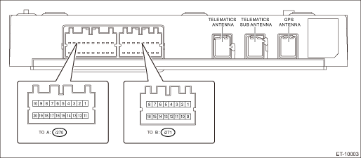
Terminal No. | Content | Measuring condition | Standard |
A1 | — | — | — |
A2 | — | — | — |
A3 | LED GREEN | — | — |
A4 ←> Chassis ground | i-button | i-button OFF > ON | 1.6 k? or more > less than 1 ? |
A5 ←> Chassis ground | SOS button | SOS button OFF > ON | 1.6 k? or more > less than 1 ? |
A6 | — | — | — |
A7 | CAN L | — | — |
A8 | Ignition power supply | Ignition switch OFF > ON | Less than 1 V > 9 — 16 V |
A9 | — | — | — |
A10 | Battery power supply | Always | 9 — 16 V |
A11 | — | — | — |
A12 | — | — | — |
A13 | LED RED | — | — |
A14 ←> Chassis ground | GND | Always | Less than 1 ? |
A15 | — | — | — |
A16 | — | — | — |
A17 | CAN H | — | — |
A18 | Airbag communication line | — | — |
A19 | MUTE | — | — |
A20 ←> Chassis ground | ACC | Ignition switch OFF > ACC ON | Less than 1 V > 9 — 16 V |
B1 | Front speaker input LH − | — | — |
B2 | Front speaker output LH − | — | — |
B3 | Front speaker input RH − | — | — |
B4 | Front speaker output RH − | — | — |
B5 | MIC signal OUT | — | — |
B6 | MIC signal | — | — |
B7 | MIC DET | — | — |
B8 | MIC 5 V | — | — |
B9 | Front speaker input LH + | — | — |
B10 | Front speaker output LH + | — | — |
B11 | Front speaker input RH + | — | — |
B12 | Front speaker output RH + | — | — |
B13 ←> Chassis ground | MIC GND OUT | Always | Less than 1 ? |
B14 | MIC GND IN | — | — |
B15 | — | — | — |
B16 | — | — | — |
 System block diagram
TELEMATICS SYSTEM (DIAGNOSTICS) > Control Module I/O SignalSYSTEM BLOCK DIAGRAMMain signals used between DCM and relevant CM ...

Other materials:
Dtc b2900 ahl control
AUTO HEADLIGHT BEAM LEVELER SYSTEM (DIAGNOSTICS) > Diagnostic Procedure with Diagnostic Trouble Code (DTC)DTC B2900 AHL CONTROLDTC DETECTING CONDITION:Detected when internal malfunction occurs in the auto headlight beam leveler CM.TROUBLE SYMPTOM:The auto headlight beam leveler does not operate.C ...
Seatbelt safety tips
WARNING
All persons in the vehicle should
fasten their seatbelts BEFORE
the vehicle starts to move. Otherwise,
the possibility of serious
injury becomes greater in the
event of a sudden stop or accident.
All belts should fit snugly in order
to provide full restraint. Loose
fittin ...
Assembly
CONTINUOUSLY VARIABLE TRANSMISSION(TR580) > Front Differential AssemblyASSEMBLY1. DIFFERENTIAL CASE ASSEMBLY1. Install the washer and differential bevel gear into the differential case (RH).2. Install the differential bevel pinions into differential case (RH) and install the pinion shaft.(A)Pinio ...
