Subaru Crosstrek Service Manual: Removal
DRIVE SHAFT SYSTEM > Front Axle
REMOVAL
1. Lift up the vehicle, and then remove the front wheels.
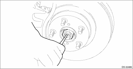
2. Remove the axle nut.
CAUTION:
Do not loosen the axle nut while the front axle is loaded. Doing so may damage the hub unit bearing.
(1) Lift the crimped section of axle nut.
(2) Remove the axle nut using a socket wrench while depressing the brake pedal.
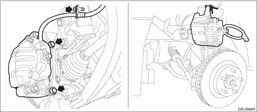
3. Remove the caliper body assembly from the front axle housing.
(1) Remove the mounting bolts and the brake hose bracket, and remove the caliper body assembly.
(2) Prepare wiring harnesses etc. to be discarded, and suspend the caliper body assembly from the strut assembly.
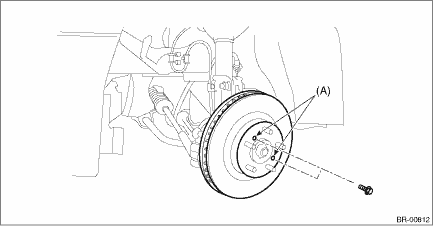
4. Remove the disc rotor.
NOTE:
When the disc rotor is difficult to be removed from the front hub unit bearing, screw in 8 mm (0.31 in) bolt to the threaded part of the disc rotor (A), and remove the disc rotor.
5. Remove the bolts, and remove the front ABS wheel speed sensor.
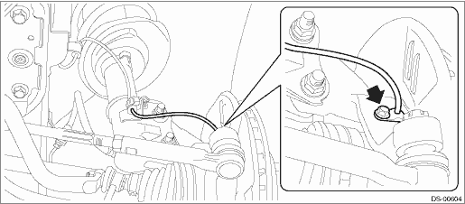
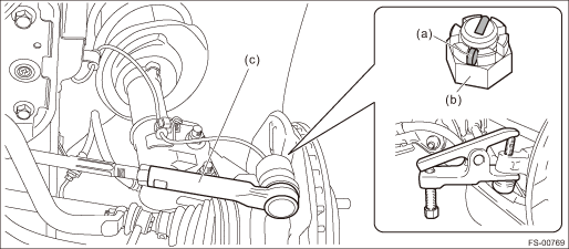
6. Disconnect the tie-rod end.
(1) Pull out the cotter pin (a).
(2) Remove the castle nut (b).
(3) Using a tie-rod ball joint puller, remove the tie-rod end (c).
CAUTION:
Be careful not to damage the boot of the joint.
Preparation tool:
Tie-rod ball joint puller
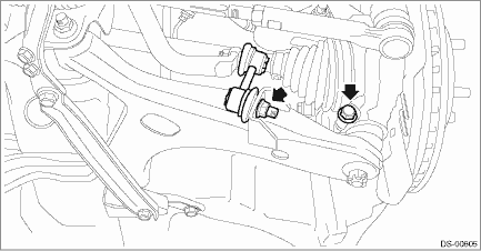
7. Remove the stabilizer link and ball joint.
CAUTION:
Be careful not to damage the boot of the joint.
8. Using a bar, remove the front drive shaft from transmission.
CAUTION:
Be careful not to allow the bar to damage holder area.
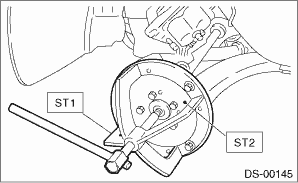
9. Remove the front drive shaft assembly from the front hub unit bearing.
NOTE:
If it is hard to remove, use the ST.
Preparation tool:
ST1: AXLE SHAFT PULLER (926470000)
ST2: AXLE SHAFT PULLER PLATE (28099PA110)
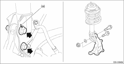
10. Remove the front axle housing.
(1) Place an alignment mark (a) on the adjusting bolt and the strut.
(2) Remove the adjusting bolts and flange bolts for the strut assembly, and then remove the front axle housing.
CAUTION:
• While holding the head of the adjusting bolt, loosen the flange nut.
• Be careful of the weight of front axle housing.
• Be careful not to damage the spline portion of the drive shaft.
11. Refer to “Front Hub Unit Bearing” for removal of the front hub unit bearing. Front Hub Unit Bearing > REMOVAL">
 Installation
DRIVE SHAFT SYSTEM > Front AxleINSTALLATION1. Install the front drive shaft assembly.CAUTION:• Do not hammer the drive shaft assembly when installing.• Use new axle nuts.(1) Insert the ...

Other materials:
Manual seat
Forward and backward adjustment
In the Subaru Ascent, adjusting the seat forward or backward is simple and designed
for precision. Lift the adjustment lever upward and smoothly slide the seat to your
preferred position. Once positioned, release the lever and gently move the seat
back and ...
Data link connector Note
ENGINE (DIAGNOSTICS)(H4DO) > Data Link ConnectorNOTEThis connector is used for Subaru Select Monitor.CAUTION:Do not connect any scan tools other than Subaru Select Monitor or general scan tool because the circuit may be damaged.Terminal No.ContentsTerminal No.Contents1Blank9Blank2Blank10Blank3Bla ...
Dtc p0400 egr "a" flow
ENGINE (DIAGNOSTICS)(H4DO) > Diagnostic Procedure with Diagnostic Trouble Code (DTC)DTC P0400 EGR "A" FLOWDTC detecting condition:Detected when two consecutive driving cycles with fault occur.Trouble symptom:• Movement performance problem when engine is low speed• Improper i ...
