Subaru Crosstrek Service Manual: Installation
DRIVE SHAFT SYSTEM > Front Axle
INSTALLATION
1. Install the front drive shaft assembly.
CAUTION:
• Do not hammer the drive shaft assembly when installing.
• Use new axle nuts.
(1) Insert the drive shaft assembly into the hub spline, and pull it into the specified position.
(2) Tighten the axle nut temporarily.
2. Install the ball joint assembly to the front axle housing.
CAUTION:
• Before tightening, make sure the lower side of front axle housing and stepped section of ball joint are in contact.
• Be careful not to damage the boot of the joint.
Tightening torque:
50 N·m (5.1 kgf-m, 36.9 ft-lb)
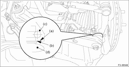
(a) | Lower side of front axle housing | (c) | Front axle housing | (d) | Ball joint ASSY |
(b) | Raised section of ball joint |
3. Install the front ABS wheel speed sensor.
Tightening torque:
7.5 N·m (0.8 kgf-m, 5.5 ft-lb)
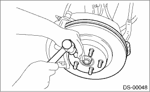
4. Install the disc rotor.
5. Install the caliper body assembly.
Tightening torque:
Refer to “COMPONENT” of “General Description” for the tightening torque. General Description > COMPONENT">
6. Install the brake hose bracket.
Tightening torque:
33 N·m (3.4 kgf-m, 24.3 ft-lb)
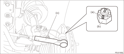
7. Install the stabilizer link.
Tightening torque:
60 N·m (6.1 kgf-m, 44.3 ft-lb)
8. Connect the tie-rod ends.
(1) Connect the tie-rod ends to the front axle housing.
(2) Tighten the castle nuts to the specified torque.
CAUTION:
When connecting the tie-rod, do not hit the cap at bottom of tie-rod end with a hammer.
Tightening torque:
27 N·m (2.8 kgf-m, 19.9 ft-lb)
(3) Tighten the castle nut within the range of 60° so that the cotter pin hole and cutout portion of the castle nut are aligned.
(4) Insert the cotter pin, and bend the tip of the pin to fix it.
9. While depressing the brake pedal, tighten a new axle nut to the specified torque and lock it securely.
CAUTION:
Do not load the front axle before tightening the axle nut. Doing so may damage the hub unit bearing.
Tightening torque:
220 N·m (22.4 kgf-m, 162.3 ft-lb)
10. After tightening the axle nut, lock it securely.
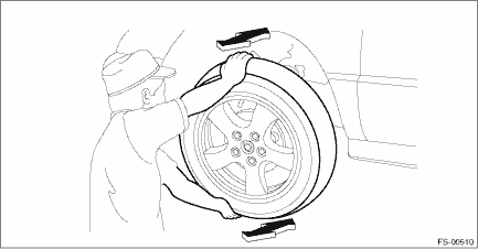
11. Install the front wheels, and perform the following inspections.
Tightening torque:
Except for C4 model: 120 N·m (12.2 kgf-m, 88.5 ft-lb)
C4 model: 100 N·m (10.2 kgf-m, 73.8 ft-lb)
(1) Check the wheels for smooth rotation.
(2) Check that there is no looseness by moving the upper and lower portions of front tire in an axial direction with the brake pedal released.
• Looseness exists > Check the front hub unit bearing. Front Hub Unit Bearing > INSPECTION">
(3) Check that there is no looseness by moving the upper and lower portions of front tire in an axial direction with the brake pedal depressed.
• Looseness exists > Replace the ball joint assembly. Front Ball Joint > REMOVAL">
12. Inspect the wheel alignment and adjust if necessary.
• Inspection: Wheel Alignment > INSPECTION">
• Adjustment: Wheel Alignment > ADJUSTMENT">
CAUTION:
When the wheel alignment has been adjusted, perform “VDC sensor midpoint setting mode”. VDC Control Module and Hydraulic Control Unit (VDCCM&H/U) > ADJUSTMENT"> VDC Control Module and Hydraulic Control Unit (VDCCM&H/U) > ADJUSTMENT"> VDC Control Module and Hydraulic Control Unit (VDCCM&H/U) > ADJUSTMENT">
13. Perform reinitialization of the auto headlight beam leveler system. (Model with auto headlight beam leveler) Auto Headlight Beam Leveler System > PROCEDURE">
 Front axle
...
 Removal
DRIVE SHAFT SYSTEM > Front AxleREMOVAL1. Lift up the vehicle, and then remove the front wheels.2. Remove the axle nut.CAUTION:Do not loosen the axle nut while the front axle is loaded. Doing so may ...
Other materials:
Dtc p0352 ignition coil "b" primary control circuit/open
ENGINE (DIAGNOSTICS)(H4DO) > Diagnostic Procedure with Diagnostic Trouble Code (DTC)DTC P0352 IGNITION COIL "B" PRIMARY CONTROL CIRCUIT/OPENNOTE:For the diagnostic procedure, refer to DTC P0351. Diagnostic Procedure with Diagnostic Trouble Code (DTC) > DTC P0351 IGNITION COIL " ...
Installation
LIGHTING SYSTEM > Headlight BulbINSTALLATIONCAUTION:Install so that the front end of the under cover (b) comes inside the bumper face - front (a), and the front end of the mud guard (c) comes outside the bumper face - front (a).1. Install each part in the reverse order of removal.2. When performi ...
Inspection
LIGHTING SYSTEM > SRF OFF SwitchINSPECTION1. Measure the resistance between connector terminals.Preparation tool:Circuit testerTerminal No.Inspection conditionsStandard2 — 3OFF1 M? or moreONLess than 1 ?2. Apply battery voltage between the connector terminals to check lighting condition of illu ...
