Subaru Crosstrek Service Manual: Installation
FRONT SUSPENSION > Front Ball Joint
INSTALLATION
1. Install the ball joint assembly to the housing assembly - front axle.
CAUTION:
• Do not apply grease to the tapered portion of ball stud.
• Before tightening, make sure the bottom surface of the housing assembly - front axle and the stepped section of ball joint are in contact.
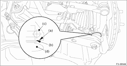
(a) | Bottom surface of housing ASSY - front axle | (c) | Housing ASSY - front axle | (d) | Ball joint ASSY |
(b) | Raised section of ball joint |
Tightening torque:
50 N·m (5.10 kgf-m, 36.9 ft-lb)
2. Install the ball joint assembly to the front arm assembly.
(1) Connect the ball joint assembly to the front arm assembly.
Tightening torque:
39 N·m (3.98 kgf-m, 28.8 ft-lb)
(2) Retighten the castle nut further up to 60° until the hole in the ball stud is aligned with a slot in castle nut.
(3) Insert a new cotter pin and bend it around the castle nut.
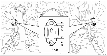
3. Install the clamp - stabilizer bushing.
CAUTION:
Install the clamp - stabilizer bushing with the arrow mark facing the front of the vehicle.
Tightening torque:
25 N·m (2.55 kgf-m, 18.4 ft-lb)
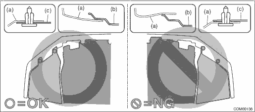
4. Install the under cover - front.
CAUTION:
Install so that the front end of the under cover (b) comes inside the bumper face - front (a), and the front end of the mud guard (c) comes outside the bumper face - front (a).
Tightening torque:
18 N·m (1.84 kgf-m, 13.3 ft-lb)
5. Install the front wheels.
Tightening torque:
Except for C4 model: 120 N·m (12.24 kgf-m, 88.5 ft-lb)
C4 model: 100 N·m (10.20 kgf-m, 73.8 ft-lb)
 Removal
FRONT SUSPENSION > Front Ball JointREMOVAL1. Lift up the vehicle, and then remove the front wheels.2. Remove the under cover - front. Front Under Cover > REMOVAL">3. Remove the clamp - ...

Other materials:
Read diagnostic trouble code (dtc) Operation
OCCUPANT DETECTION SYSTEM (DIAGNOSTICS) > Read Diagnostic Trouble Code (DTC)OPERATIONRead out DTCs stored in the airbag system and the occupant detection system.1. AIRBAG SYSTEM1. On «Start» display, select «Diagnosis».2. On «Vehicle selection» display, input the target vehicle information ...
Automatic engine shutdown
The remote engine start system will
automatically shut down or will not start
the engine under the following conditions.
The total run-time has exceeded 20
minutes.
Any door or the rear gate is opened.
The select lever is moved to any
position other than "P".
The engine hood is opene ...
SRS airbag (Supplemental Restraint System airbag)
*SRS: This stands for supplemental restraint
system. This name is used because
the airbag system supplements the
vehicle's seatbelts.
Your vehicle is equipped with a supplemental
restraint system in addition to a
lap/shoulder belt at each front seating
position and each rear window-side sea ...
