Subaru Crosstrek Service Manual: Installation
DRIVE SHAFT SYSTEM > Rear Hub Unit Bearing
INSTALLATION
1. Place the rear brake back plate between the rear axle housing and the rear hub unit bearing, and tighten the bolt.
CAUTION:
• Be careful not to damage the magnetic encoder.
• Do not get closer the tool which charged magnetism to magnetic encoder.
• Use a new bolt.
Tightening torque:
65 N·m (6.6 kgf-m, 47.9 ft-lb)
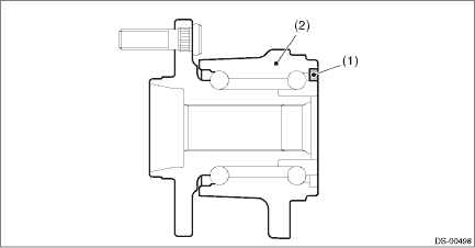
(1) | Magnetic encoder | (2) | Rear hub unit bearing |
(a) | Rear axle housing | (b) | Rear brake back plate | (c) | Rear hub unit bearing |
2. Install the rear drive shaft assembly.
CAUTION:
• Do not hammer the drive shaft assembly when installing.
• Use new axle nuts.
(1) Insert the drive shaft assembly into the hub spline, and pull it into the specified position.
(2) Tighten the axle nut temporarily.
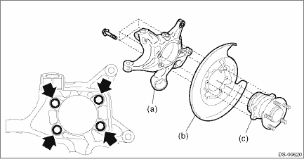
3. Install the disc rotor to the rear hub unit bearing.
4. Install the caliper body assembly to the rear axle housing.
Tightening torque:
Refer to “COMPONENT” of “General Description” for the tightening torque. General Description > COMPONENT">
5. Install the brake hose bracket.
Tightening torque:
33 N·m (3.4 kgf-m, 24.3 ft-lb)
6. Install the rear ABS wheel speed sensor.
Tightening torque:
7.5 N·m (0.8 kgf-m, 5.5 ft-lb)
7. While pressing the brake pedal, tighten the new axle nuts to the specified torque.
CAUTION:
Do not load the rear axle before tightening the axle nut. Doing so may damage the hub unit bearing.
Tightening torque:
190 N·m (19.4 kgf-m, 140.1 ft-lb)
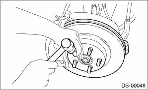
8. After tightening the axle nut, lock it securely.
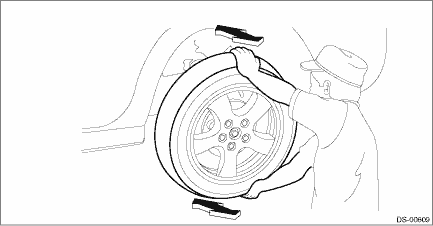
9. Install the rear wheels, and perform the following inspections.
Tightening torque:
Except for C4 model: 120 N·m (12.2 kgf-m, 88.5 ft-lb)
C4 model: 100 N·m (10.2 kgf-m, 73.8 ft-lb)
(1) Check the wheels for smooth rotation.
(2) Check that there is no looseness by moving the upper and lower portions of rear tire in an axial direction with the brake pedal released.
• Looseness exists > Check the rear hub unit bearing. Rear Hub Unit Bearing > INSPECTION">
 Inspection
DRIVE SHAFT SYSTEM > Rear Hub Unit BearingINSPECTION1. Moving the rear tire up and down by hand, check there is no looseness in bearing, and check the wheel rotates smoothly.CAUTION:If there is uns ...
 General diagnostic table Inspection
DRIVE SHAFT SYSTEM > General Diagnostic TableINSPECTIONNOTE:Vibration while cruising may be caused by an unbalanced tire, improper tire inflation pressure, improper wheel alignment, etc.SymptomsPos ...
Other materials:
BSD/RCTA OFF indicator
System temporary stops
BSD/RCTA temporary stop message
BSD/RCTA OFF indicator
In the Subaru Ascent, this message is displayed when the BSD/RCTA system is temporarily
suspended due to external or internal conditions that prevent accurate operation.
Extremely high or extremely low a ...
Dtc b1010 body control system (biu) malfunction
BODY CONTROL SYSTEM (DIAGNOSTICS) > Diagnostic Procedure with Diagnostic Trouble Code (DTC)DTC B1010 BODY CONTROL SYSTEM (BIU) MALFUNCTIONDTC DETECTING CONDITION:System error in body integrated unitTROUBLE SYMPTOM:LAN communication immobilizer function may not be executed normally.STEPCHECKYESNO1 ...
Clear memory mode Operation
AUTO HEADLIGHT BEAM LEVELER SYSTEM (DIAGNOSTICS) > Clear Memory ModeOPERATION1. On «Start» display, select «Diagnosis».2. On «Vehicle selection» display, input the target vehicle information and select «Confirmed».3. On «Main Menu» display, select «Each System».4. On «Select System» ...
