
Subaru Crosstrek Service Manual: Installation
CONTINUOUSLY VARIABLE TRANSMISSION(TR580) > Oil Pump Chain
INSTALLATION
1. Clean the mating surface of oil pump chain cover and converter case.
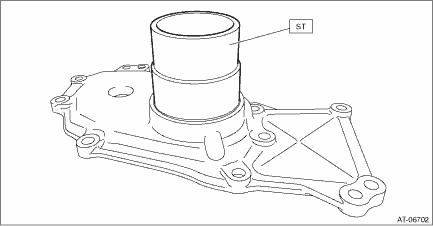
2. Using the ST, install the oil seal.
NOTE:
• Use a new oil seal.
• Apply CVTF to the oil seal lip and press-fitting surface.
| ST 499755602 | PRESS SNAP RING |
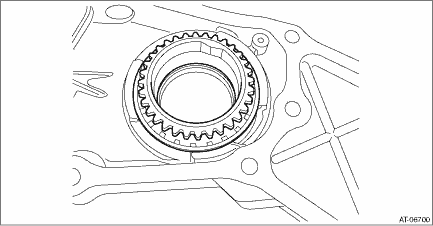
3. Install the drive sprocket.
4. Install the snap ring so that its cutout portion is securely fitted into the snap ring groove of the oil pump chain cover.
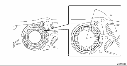
(A) | Installation range of cutout portion for snap ring |
5. Place the oil pump chain on drive sprocket.
6. Place the oil pump chain on driven sprocket and install the driven sprocket to oil pump chain cover.
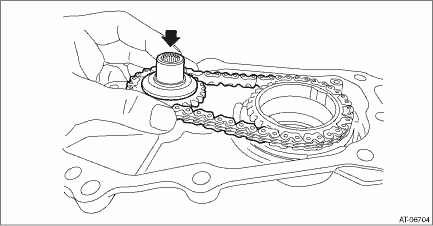
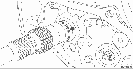
7. Install the seal ring.
NOTE:
• Use a new seal ring.
• Apply CVTF to the seal rings.
• When installing the seal ring, do not expand the seal ring too much.
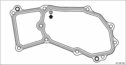
8. Apply liquid gasket seamlessly to the mating surface of oil pump chain cover.
CAUTION:
Do not apply liquid gasket at the arrowed hole.
Liquid gasket:
THREE BOND 1215B or equivalent
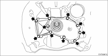
9. Install the oil pump chain cover.
Tightening torque:
21 N·m (2.1 kgf-m, 15.5 ft-lb)
10. Install the torque converter assembly. Torque Converter Assembly > INSTALLATION">
11. Install the transmission assembly to the vehicle. Automatic Transmission Assembly > INSTALLATION">
 Inspection
CONTINUOUSLY VARIABLE TRANSMISSION(TR580) > Oil Pump ChainINSPECTION• Check the oil pump chain for damage.• Replace if gear teeth are broken, damaged, sharpen or excessively worn.• ...
 Parking pawl
...
Other materials:
HomeLink Wireless Control System
The HomeLink Wireless Control System in the Subaru Ascent offers a highly convenient
and integrated solution for replacing up to three separate hand-held radio-frequency
remotes. This advanced system allows drivers to control various devices such as
garage door openers, automatic gates, entry ...
Adjustment
LIGHTING SYSTEM > Front Fog Light AssemblyADJUSTMENT1. FOG LIGHT AIMING1. Before checking the fog light assembly - front beam level, be sure of the following:• The area around the fog light assembly - front has not sustained any scratches, damage or other type of deformation.• The veh ...
Electrical specification
POWER ASSISTED SYSTEM (POWER STEERING) (DIAGNOSTICS) > Control Module I/O SignalELECTRICAL SPECIFICATIONNOTE:The terminal numbers of the power steering control module connectors are as indicated in the figure.ContentsTerminal No.Input/output signalMeasured value and measuring conditionsPower supp ...
