Subaru Crosstrek Service Manual: Installation
BRAKE > Front Disc Brake Assembly
INSTALLATION
NOTE:
Before installation, remove mud and foreign matter from the caliper body assembly and support - front disc brake.
1. Check each part. Front Disc Brake Assembly > INSPECTION">
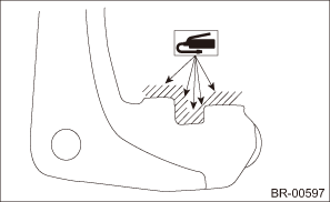
2. Apply a thin coat of grease to the support - front disc brake.
Preparation items:
Grease: An item contained in the pad kit or equivalent
3. Install the support - front disc brake to the housing assembly - front axle.
Tightening torque:
Refer to “COMPONENT” of “General Description” for the tightening torque. General Description > COMPONENT">
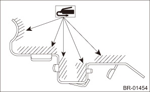
4. Apply a thin coat of grease to the pad clip.
Preparation items:
Grease: An item contained in the pad kit or equivalent
5. Install the brake pad to the support - front disc brake.
CAUTION:
• Be sure to install so that the pad return spring faces the input side of the direction of brake rotor rotation, as shown in the figure.
• Correctly install the pad return spring to the supporting surface of the pad clip as shown in the figure.
• If the pad return spring is deformed or damaged, replace the brake pad with a new part.
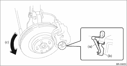
(a) | Pad return spring | (b) | Supporting surface of pad clip | (c) | Direction of brake rotor rotation |
NOTE:
Install the brake pad indicator in proper direction.
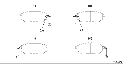
(a) | LH — IN | (c) | RH — IN | (e) | Pad indicator |
(b) | LH — OUT | (d) | RH — OUT | (f) | Pad return spring |
6. Install the caliper body assembly to the support - front disc brake.
Tightening torque:
Caliper bolt: 27 N·m (2.75 kgf-m, 19.9 ft-lb)
7. Connect the brake hose using a new brake hose gasket.
Tightening torque:
Union bolt: 26 N·m (2.65 kgf-m, 19.2 ft-lb)
8. Bleed air from the brake system. Air Bleeding > PROCEDURE">
9. Install the front wheels.
Tightening torque:
Except for C4 model: 120 N·m (12.24 kgf-m, 88.5 ft-lb)
C4 model: 100 N·m (10.20 kgf-m, 73.8 ft-lb)
 Inspection
BRAKE > Front Disc Brake AssemblyINSPECTION1. Check the caliper body cylinder and piston for uneven wear, damage or rust.2. Check the rubber parts for damage or deterioration.3. If faulty is found ...
 Front disc rotor
...
Other materials:
Check list for interview Check
AUTO HEADLIGHT BEAM LEVELER SYSTEM (DIAGNOSTICS) > Check List for InterviewCHECK• Inspect the following items regarding the vehicle’s state.• Print out this page for interviewing customers.Auto Headlight Beam Leveler System Check List for Interview ...
Power saving function
The Subaru Ascent includes an intelligent power-saving feature designed to protect
both the vehicle battery and the access key fob battery by automatically disabling
the keyless access system under certain conditions.
When the Subaru Ascent keyless access system has not been used for two wee ...
Inspection
CONTINUOUSLY VARIABLE TRANSMISSION(TR580) > Transmission HarnessINSPECTION1. Visually check the harness and connector for damage or crack.2. Check the harness terminal for rust, disconnection or poor contact.3. Check the continuity between harness terminals.NOTE:For details of transmission harnes ...
