Subaru Crosstrek Service Manual: Inspection
VEHICLE DYNAMICS CONTROL (VDC) (DIAGNOSTICS) > Subaru Select Monitor
INSPECTION
1. COMMUNICATION FOR INITIALIZING IMPOSSIBLE
Detecting condition:
Defective harness connector
Trouble symptom:
Communication is impossible between VDC and Subaru Select Monitor.
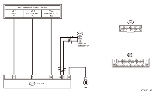
WIRING DIAGRAM:
Models without EyeSight
Vehicle dynamics control system Vehicle Dynamics Control System > WIRING DIAGRAM">
| STEP | CHECK | YES | NO |
1.CHECK IGNITION SWITCH.
Is the ignition switch ON?
Subaru Select Monitor > INSPECTION">Go to Step 2.
Turn the ignition switch to ON, and select VDC using the Subaru Select Monitor.
2.CHECK BATTERY.
1) Turn the ignition switch to OFF.
2) Measure the battery voltage.
Is the voltage 11 V or more?
Subaru Select Monitor > INSPECTION">Go to Step 3.
Charge or replace the battery.
3.CHECK BATTERY TERMINAL.
Is there poor contact at battery terminal?
Replace or tighten the battery terminal.
Subaru Select Monitor > INSPECTION">Go to Step 4.
4.CHECK INSTALLATION OF VDCCM&H/U CONNECTOR.
Turn the ignition switch to OFF.
Is the VDCCM&H/U connector inserted into VDCCM&H/U until the clamp locks onto it?
Subaru Select Monitor > INSPECTION">Go to Step 5.
Insert VDCCM&H/U connector into VDCCM&H/U.
5.CHECK LAN SYSTEM.
Perform the diagnosis for LAN system. Basic Diagnostic Procedure">
Is there any fault in LAN system?
Perform the diagnosis according to DTC for LAN system. List of Diagnostic Trouble Code (DTC)">
Subaru Select Monitor > INSPECTION">Go to Step 6.
6.CHECK SUBARU SELECT MONITOR COMMUNICATION.
1) Turn the ignition switch to ON.
2) Check whether communication to VDC system can be executed normally.
Is the system name displayed on Subaru Select Monitor?
Check the DTC in VDC system. Read Diagnostic Trouble Code (DTC)">
Subaru Select Monitor > INSPECTION">Go to Step 7.
7.CHECK POWER SUPPLY CIRCUIT.
1) Turn the ignition switch to ON. (Engine OFF)
2) Measure the ignition power supply voltage between VDCCM&H/U connector and chassis ground.
Connector & terminal
(B310) No. 1 (+) — Chassis ground (−):
(B310) No. 25 (+) — Chassis ground (−):
(B310) No. 28 (+) — Chassis ground (−):
Is the voltage 10 — 15 V?
Subaru Select Monitor > INSPECTION">Go to Step 8.
Repair open circuit in harness between VDCCM&H/U and battery.
8.CHECK HARNESS CONNECTOR BETWEEN VDCCM&H/U AND CHASSIS GROUND.
1) Turn the ignition switch to OFF.
2) Disconnect the connector from the VDCCM&H/U.
3) Measure the resistance of harness between VDCCM&H/U connector and chassis ground.
Connector & terminal
(B310) No. 38 — Chassis ground:
Is the resistance less than 10 ??
Subaru Select Monitor > INSPECTION">Go to Step 9.
Repair the open circuit of VDCCM&H/U ground circuit and poor contact of connector.
9.CHECK POOR CONTACT OF CONNECTOR.
Is there poor contact of control module power supply, ground circuit and data link connector?
Repair the connector.
Replace the VDCCM&H/U. VDC Control Module and Hydraulic Control Unit (VDCCM&H/U)">
Models with EyeSight
Vehicle dynamics control system Vehicle Dynamics Control System > WIRING DIAGRAM">

| STEP | CHECK | YES | NO |
1.CHECK IGNITION SWITCH.
Is the ignition switch ON?
Subaru Select Monitor > INSPECTION">Go to Step 2.
Turn the ignition switch to ON, and select VDC using the Subaru Select Monitor.
2.CHECK BATTERY.
1) Turn the ignition switch to OFF.
2) Measure the battery voltage.
Is the voltage 11 V or more?
Subaru Select Monitor > INSPECTION">Go to Step 3.
Charge or replace the battery.
3.CHECK BATTERY TERMINAL.
Is there poor contact at battery terminal?
Replace or tighten the battery terminal.
Subaru Select Monitor > INSPECTION">Go to Step 4.
4.CHECK INSTALLATION OF VDCCM&H/U CONNECTOR.
Turn the ignition switch to OFF.
Is the VDCCM&H/U connector inserted into VDCCM&H/U until the clamp locks onto it?
Subaru Select Monitor > INSPECTION">Go to Step 5.
Insert VDCCM&H/U connector into VDCCM&H/U.
5.CHECK SUBARU SELECT MONITOR COMMUNICATION.
1) Turn the ignition switch to ON.
2) Using the Subaru Select Monitor, check whether communication to other systems can be executed normally.
Is the system name displayed on Subaru Select Monitor?
Subaru Select Monitor > INSPECTION">Go to Step 9.
Subaru Select Monitor > INSPECTION">Go to Step 6.
6.CHECK SUBARU SELECT MONITOR COMMUNICATION.
1) Turn the ignition switch to OFF.
2) Disconnect the VDCCM&H/U connector.
3) Turn the ignition switch to ON.
4) Check whether communication to other systems can be executed normally.
Is the system name displayed on Subaru Select Monitor?
Replace the VDCCM&H/U. VDC Control Module and Hydraulic Control Unit (VDCCM&H/U)">
Subaru Select Monitor > INSPECTION">Go to Step 7.
7.CHECK HARNESS CONNECTOR BETWEEN EACH CONTROL MODULE AND DATA LINK CONNECTOR.
1) Turn the ignition switch to OFF.
2) Disconnect the connectors from ECM, TCM, power steering CM, airbag CM and impact sensor.
CAUTION:
When disconnecting the connector from airbag CM, always follow the precautions on AB section. General Description > CAUTION">
3) Measure the resistance between data link connector and chassis ground.
Connector & terminal
(B40) No. 7 — Chassis ground:
Is the resistance 1 M? or more?
Subaru Select Monitor > INSPECTION">Go to Step 8.
Repair the harness and connector between each control module and data link connector.
8.CHECK HARNESS CONNECTOR BETWEEN VDCCM&H/U AND DATA LINK CONNECTOR.
1) Turn the ignition switch to ON.
2) Measure the voltage between data link connector and chassis ground.
Connector & terminal
(B40) No. 7 (+) — Chassis ground (−):
Is the voltage less than 1 V?
Subaru Select Monitor > INSPECTION">Go to Step 9.
Repair the harness and connector between each control module and data link connector.
9.CHECK HARNESS CONNECTOR BETWEEN VDCCM&H/U AND DATA LINK CONNECTOR.
Measure the resistance between VDCCM&H/U connector and data link connector.
Connector & terminal
(B310) No. 18 — (B40) No. 7:
Is the resistance less than 1 ??
Subaru Select Monitor > INSPECTION">Go to Step 10.
Repair harness and connector between VDCCM&H/U and data link connector.
10.CHECK POWER SUPPLY CIRCUIT.
1) Turn the ignition switch to ON. (Engine OFF)
2) Measure the ignition power supply voltage between VDCCM&H/U connector and chassis ground.
Connector & terminal
(B310) No. 1 (+) — Chassis ground (−):
(B310) No. 14 (+) — Chassis ground (−):
(B310) No. 20 (+) — Chassis ground (−):
Is the voltage 10 — 15 V?
Subaru Select Monitor > INSPECTION">Go to Step 11.
Repair open circuit in harness between VDCCM&H/U and battery.
11.CHECK HARNESS CONNECTOR BETWEEN VDCCM&H/U AND CHASSIS GROUND.
1) Turn the ignition switch to OFF.
2) Disconnect the connector from the VDCCM&H/U.
3) Measure the resistance of harness between VDCCM&H/U connector and chassis ground.
Connector & terminal
(B310) No. 26 — Chassis ground:
Is the resistance less than 10 ??
Subaru Select Monitor > INSPECTION">Go to Step 12.
Repair the open circuit of VDCCM&H/U ground harness and poor contact of connector.
12.CHECK POOR CONTACT OF CONNECTOR.
Is there poor contact of control module power supply, ground circuit and data link connector?
Repair the connector.
Replace the VDCCM&H/U. VDC Control Module and Hydraulic Control Unit (VDCCM&H/U)">

 Operation
VEHICLE DYNAMICS CONTROL (VDC) (DIAGNOSTICS) > Subaru Select MonitorOPERATION1. HOW TO USE SUBARU SELECT MONITORFor detailed operation procedures, refer to “Application help”.2. READ CU ...
Other materials:
Automatic engine shutdown
The remote engine start system will
automatically shut down or will not start
the engine under the following conditions.
The total run-time has exceeded 20
minutes.
Any door or the rear gate is opened.
The select lever is moved to any
position other than "P".
The engine hood is opene ...
Dtc p2096 post catalyst fuel trim system too lean bank 1
ENGINE (DIAGNOSTICS)(H4DO) > Diagnostic Procedure with Diagnostic Trouble Code (DTC)DTC P2096 POST CATALYST FUEL TRIM SYSTEM TOO LEAN BANK 1DTC detecting condition:Detected when two consecutive driving cycles with fault occur.CAUTION:After servicing or replacing faulty parts, perform Clear Memory ...
Installation
SECURITY AND LOCKS > Steering Lock CMINSTALLATIONCAUTION:• When the control module related to immobilizer has been replaced, be sure to perform the registration of immobilizer system. For detailed operation procedure, refer to “Type D” described in “REGISTRATION MANUAL FOR ...
