Subaru Crosstrek Service Manual: Inspection
ENTERTAINMENT > Navigation System
INSPECTION
1. BASIC INSPECTION
1. Using the Check List for Interview, ask the customer the condition of how the trouble occurred. Check List for Interview > CHECK">
2. Check the battery. Battery > INSPECTION">
3. Check the list of Diagnostics with Phenomenon, and perform diagnosis according to the procedures. Diagnostics with Phenomenon > LIST">
2. SYSTEM BLOCK DIAGRAM
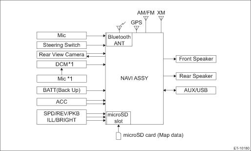
*1: Model with telematics
3. MODULE I/O SIGNAL
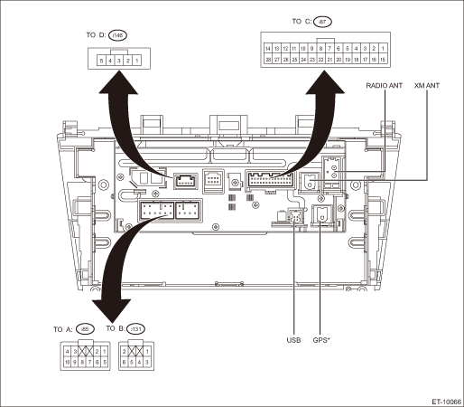
*: Model with navigation system
• Power supply and speaker output terminal
Terminal No. | Content | Measuring condition | Measurement value | Note |
(i85) No. 1 | FRONT-RH (+) | — | — | — |
(i85) No. 2 | FRONT-LH (+) | — | — | — |
(i85) No. 3 ←> Chassis ground | ACC | ACC ON | 11 — 15 V | — |
(i85) No. 4 ←> Chassis ground | +B | Always | 11 — 15 V | — |
(i85) No. 5 | FRONT-RH (−) | — | — | — |
(i85) No. 6 | FRONT-LH (−) | — | — | — |
(i85) No. 7 ←> Chassis ground | GND | Always | 0 V | — |
(i85) No. 8 | ANTENNA-ON | — | — | — |
(i85) No. 9 | N.C. | — | — | — |
(i85) No. 10 | ILLUMI (+) | — | — | — |
(i131) No. 1 | REAR-RH (+) | — | — | — |
(i131) No. 2 | REAR-LH (+) | — | — | — |
(i131) No. 3 | REAR-RH (−) | — | — | — |
(i131) No. 4 | N.C. | — | — | — |
(i131) No. 5 | ILLUMI (−) | — | — | — |
(i131) No. 6 | REAR-LH (−) | — | — | — |
• Steering switch and AUX input terminal for microphone etc.
Terminal No. | Content | Measuring condition | Measurement value | Note |
(i87) No. 1 ←> Chassis ground | N.C. | — | — | — |
(i87) No. 2 | REV | — | — | — |
(i87) No. 3 | BRIGHT | — | — | — |
(i87) No. 4 | MACC | — | — | — |
(i87) No. 5 | MIC+ | — | — | — |
(i87) No. 6 | MIC-DET | — | — | — |
(i87) No. 7 | N.C. | — | — | — |
(i87) No. 8 | N.C. | — | — | — |
(i87) No. 9 | N.C. | — | — | — |
(i87) No. 10 | N.C. | — | — | — |
(i87) No. 11 | N.C. | — | — | — |
(i87) No. 12 | N.C. | — | — | — |
(i87) No. 13 | N.C. | — | — | — |
(i87) No. 14 | N.C. | — | — | — |
(i87) No. 15 ←> Chassis ground | PKB | At parking ON | 1 V or less | — |
(i87) No. 16 | N.C. | — | — | — |
(i87) No. 17 ←> Chassis ground | SPD | When the tire is rotating | Pulse signal | — |
(i87) No. 18 | N.C. | — | — | — |
(i87) No. 19 | MIC- | — | — | — |
(i87) No. 20 | N.C. | — | — | — |
(i87) No. 21 | SW1 | — | — | — |
(i87) No. 22 | SW2 | — | — | — |
(i87) No. 23 | SWG | — | — | — |
(i87) No. 24 | N.C. | — | — | — |
(i87) No. 25 | AUX-DET | — | — | — |
(i87) No. 26 | AUX-R (+) | — | — | — |
(i87) No. 27 | AUX-LR (−) | — | — | — |
(i87) No. 28 | AUX-L (+) | — | — | — |
• Rearview camera
Terminal No. | Content | Measuring condition | Measurement value | Note |
(i146) No. 1 ←> Chassis ground | CGND | Always | 0 V | — |
(i146) No. 2 | CB+ | — | — | — |
(i146) No. 3 | CV+ | — | — | — |
(i146) No. 4 | CV− | — | — | — |
(i146) No. 5 | N.C. | — | — | — |

 Wiring diagram
ENTERTAINMENT > Navigation SystemWIRING DIAGRAMRefer to “Navigation System” in the wiring diagram.• Model without telematics: Navigation System > WIRING DIAGRAM">&bull ...
Other materials:
Washing the underbody
Chemicals, salts and gravel used for
deicing road surfaces are extremely corrosive,
accelerating the corrosion of underbody
components, such as the exhaust
system, fuel and brake lines, brake
cables, floor pan and fenders, and suspension.
Thoroughly flush the underbody and inside
of the fen ...
Note
VEHICLE DYNAMICS CONTROL (VDC) > Vehicle Dynamics Control SystemNOTEFor operation procedures of each component of the vehicle dynamics control system, refer to the respective section.• VDC control module & hydraulic control unit (VDCCM&H/U): VDC Control Module and Hydraulic Control ...
Schedule Maintenance schedule
PERIODIC MAINTENANCE SERVICES > ScheduleMAINTENANCE SCHEDULE1. MODEL WITH US SPECIFICATIONMaintenance itemMaintenance interval[Number of months or km (miles), whichever occurs first] Months3612182430364248546066To be continued to the next table.Remarks? 1,000 km4.89.619.228.838.44857.667.276.886. ...
