Subaru Crosstrek Service Manual: Dtc p1530 battery current sensor circuit low
ENGINE (DIAGNOSTICS)(H4DO) > Diagnostic Procedure with Diagnostic Trouble Code (DTC)
DTC P1530 BATTERY CURRENT SENSOR CIRCUIT LOW
DTC detecting condition:
Immediately at fault recognition
CAUTION:
After servicing or replacing faulty parts, perform Clear Memory Mode Clear Memory Mode > OPERATION"> , and Inspection Mode Inspection Mode > PROCEDURE">.
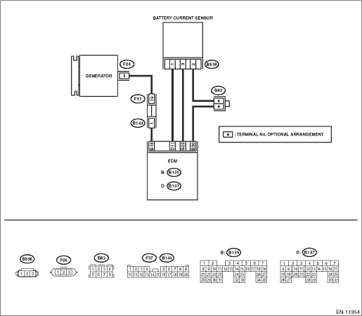
Wiring diagram:
Engine electrical system Engine Electrical System">
| STEP | CHECK | YES | NO |
1.CHECK CURRENT DATA.
1) Start the engine.
2) Read the value of «Battery current value» using the Subaru Select Monitor.
NOTE:
For detailed operation procedures, refer to “Current Data Display For Engine”. Subaru Select Monitor">
Is the value of «Battery current value» −100 A or less?
Diagnostic Procedure with Diagnostic Trouble Code (DTC) > DTC P1530 BATTERY CURRENT SENSOR CIRCUIT LOW">Go to Step 2.
Even if DTC is detected, the circuit has returned to a normal condition at this time. Reproduce the failure, and then perform the diagnosis again.
NOTE:
In this case, temporary poor contact of connector, temporary open or short circuit of harness may be the cause.
2.CHECK HARNESS BETWEEN ECM AND BATTERY CURRENT SENSOR CONNECTOR.
1) Turn the ignition switch to OFF.
2) Disconnect the connector from ECM.
3) Disconnect the connector from the battery current sensor.
4) Measure the resistance of the harness between ECM connector and battery current sensor connector.
Connector & terminal
(B135) No. 22 — (B538) No. 3:
(B137) No. 11 — (B538) No. 1:
Is the resistance less than 1 ??
Diagnostic Procedure with Diagnostic Trouble Code (DTC) > DTC P1530 BATTERY CURRENT SENSOR CIRCUIT LOW">Go to Step 3.
Repair the open circuit in the harness between ECM connector and battery current sensor connector.
3.CHECK HARNESS BETWEEN ECM AND BATTERY CURRENT SENSOR CONNECTOR.
Measure the resistance between ECM connector and chassis ground.
Connector & terminal
(B135) No. 22 — Chassis ground:
(B137) No. 11 — Chassis ground:
Is the resistance 1 M? or more?
Diagnostic Procedure with Diagnostic Trouble Code (DTC) > DTC P1530 BATTERY CURRENT SENSOR CIRCUIT LOW">Go to Step 4.
Repair the short circuit to ground in the harness between ECM connector and battery current sensor connector.
4.CHECK FOR POOR CONTACT.
Check for poor contact between the ECM and battery current sensor connectors.
Is there poor contact of the ECM or battery current sensor connectors?
Repair any poor contact between the ECM and battery current sensor connectors.
Replace the battery current sensor. Battery Current & Temperature Sensor">
1. OUTLINE OF DIAGNOSIS
Detect the open or short circuit of battery current sensor.
Judge as NG if out of specification.
2. COMPONENT DESCRIPTION
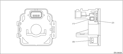
(1) | Hall IC | (2) | Chip condenser | (3) | Core |
3. EXECUTION CONDITION
Secondary Parameters | Execution condition |
Battery voltage | ≥ 10.9 V |
Elapsed time after starting the engine | > 1000 ms |
Engine speed | > 500 rpm |
Ignition switch | ON |
4. GENERAL DRIVING CYCLE
Always perform the diagnosis continuously.
5. DIAGNOSTIC METHOD
If the duration of time while the following conditions are met is longer than the time indicated, judge as NG.
Malfunction Criteria | Threshold Value |
Output voltage | < 0.2148 V |
Time Needed for Diagnosis: 500 ms
Malfunction Indicator Light Illumination: Does not illuminate even when malfunction occurs.
 Dtc p0517 battery temperature sensor circuit high
ENGINE (DIAGNOSTICS)(H4DO) > Diagnostic Procedure with Diagnostic Trouble Code (DTC)DTC P0517 BATTERY TEMPERATURE SENSOR CIRCUIT HIGHDTC detecting condition:Immediately at fault recognitionCAUTION: ...
 Dtc p1531 battery current sensor circuit high
ENGINE (DIAGNOSTICS)(H4DO) > Diagnostic Procedure with Diagnostic Trouble Code (DTC)DTC P1531 BATTERY CURRENT SENSOR CIRCUIT HIGHDTC detecting condition:Immediately at fault recognitionCAUTION:Afte ...
Other materials:
Braking tips
WARNING
Never rest your foot on the brake
pedal while driving. This can cause
dangerous overheating of the
brakes and needless wear on the
brake pads and linings.
When the brakes get wet
When driving in rain or after washing the
vehicle, the brakes may get wet. As a
result, brake stopping d ...
SUBARU advanced frontal airbag system
Your vehicle is equipped with a SUBARU
advanced frontal airbag system that complies
with the new advanced frontal airbag
requirements in the amended Federal
Motor Vehicle Safety Standard (FMVSS)
No. 208.
The SUBARU advanced frontal airbag
system automatically determines the deployment
forc ...
Dtc p000c "a" camshaft position slow response bank 2
ENGINE (DIAGNOSTICS)(H4DO) > Diagnostic Procedure with Diagnostic Trouble Code (DTC)DTC P000C "A" CAMSHAFT POSITION SLOW RESPONSE BANK 2NOTE:For the diagnostic procedure, refer to DTC P0021. Diagnostic Procedure with Diagnostic Trouble Code (DTC) > DTC P0021 "A" CAMSHAFT P ...
