Subaru Crosstrek Service Manual: Dtc p0400 egr "a" flow
ENGINE (DIAGNOSTICS)(H4DO) > Diagnostic Procedure with Diagnostic Trouble Code (DTC)
DTC P0400 EGR "A" FLOW
DTC detecting condition:
Detected when two consecutive driving cycles with fault occur.
Trouble symptom:
• Movement performance problem when engine is low speed
• Improper idling
• Movement performance problem
CAUTION:
After servicing or replacing faulty parts, perform Clear Memory Mode Clear Memory Mode > OPERATION"> , and Inspection Mode Inspection Mode > PROCEDURE">.
| STEP | CHECK | YES | NO |
1.CHECK CURRENT DATA.
1) Start the engine.
2) Read the value of «Mani. Absolute Pressure» using the Subaru Select Monitor or a general scan tool.
NOTE:
• Subaru Select Monitor
For detailed operation procedures, refer to “Current Data Display For Engine”. Subaru Select Monitor">
• General scan tool
For detailed operation procedures, refer to the general scan tool operation manual.
Is the value of «Mani. Absolute Pressure» 53.3 kPa (400 mmHg, 15.75 inHg) or more?
Make sure that the EGR control valve, manifold absolute pressure sensor and throttle body are installed securely.
Diagnostic Procedure with Diagnostic Trouble Code (DTC) > DTC P0400 EGR "A" FLOW">Go to Step 2.
2.CHECK EGR CONTROL VALVE.
Remove the EGR control valve.
Are there any holes, clogged lines or foreign matters in the EGR system?
Repair the EGR system.
Replace EGR control valve. EGR Control Valve">
1. OUTLINE OF DIAGNOSIS
Detect EGR system malfunction.
Intake manifold pressure (negative pressure) is constant because the throttle valve is fully closed during deceleration fuel cut. At this time, when the EGR control valve is opened/closed, the intake manifold pressure will change. EGR System OK/NG is judged by the range of this change.
2. COMPONENT DESCRIPTION
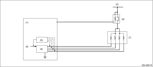
(1) | Engine control module (ECM) | (4) | Switching circuit | (6) | Main relay |
(2) | Computer unit (CPU) | (5) | Battery voltage | (7) | EGR control valve |
(3) | Detecting circuit |
3. EXECUTION CONDITION
Secondary parameters | Execution condition |
Battery voltage | ≥ 10.9 V |
Barometric pressure | ≥ 75.1 kPa (563 mmHg, 22.2 inHg) |
Intake air temperature | ≥ 0 °C(32 °F) |
Engine speed | 1300 rpm — 5000 rpm |
Vehicle speed | ≥40 km/h (24.9 MPH) |
Elapsed time after fuel cut | ≥ 3000 ms |
Neutral switch | = OFF |
4. GENERAL DRIVING CYCLE
During deceleration fuel cut from 40 km/h (approx. 24.9 MPH) or more, perform diagnosis once.
Be careful of vehicle speed and engine speed. (Diagnosis will not be completed if the vehicle speed and engine speed conditions become out of specification due to deceleration.)
5. DIAGNOSTIC METHOD
Measure the pressure values when the enable conditions are established, and perform diagnosis by calculating those results.
(1) Label the intake manifold pressure value as PMOF1, which is observed when enable conditions are established, and set the EGR target step to 45 step(s) (nearly full open).
(2) Label the intake manifold pressure value as PMON, which is observed after 1000 ms has passed since EGR target step was set to 45 step(s) (when the enable conditions were established), and set the EGR target step to 0.
(3) Label the intake manifold pressure as PMOF2, which is observed after 1000 ms has passed since EGR target step was set to 0 (after (1000 ms + 1000 ms) have passed since the enable conditions were established).
Judge as NG when the following conditions are established.
Malfunction Criteria | Threshold Value |
PMON − (PMOF1 + PMOF2)/2 | < 2.5 kPa (18.63 mmHg, 0.7 inHg) |
Time Needed for Diagnosis: 2 seconds
Malfunction Indicator Light Illumination: Illuminates when malfunction occurs in 2 continuous driving cycles.
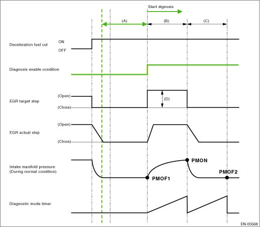
(A) | 3000 ms | (B) | 1000 ms | (C) | 1000 ms |
(D) | 45 step(s) |
 Dtc p0391 camshaft position sensor "b" circuit range/performance bank 2
ENGINE (DIAGNOSTICS)(H4DO) > Diagnostic Procedure with Diagnostic Trouble Code (DTC)DTC P0391 CAMSHAFT POSITION SENSOR "B" CIRCUIT RANGE/PERFORMANCE BANK 2NOTE:For the diagnostic procedur ...
 Dtc p0420 catalyst system efficiency below threshold bank 1
ENGINE (DIAGNOSTICS)(H4DO) > Diagnostic Procedure with Diagnostic Trouble Code (DTC)DTC P0420 CATALYST SYSTEM EFFICIENCY BELOW THRESHOLD BANK 1DTC detecting condition:Detected when two consecutive ...
Other materials:
Removal
REAR SUSPENSION > Front Lateral LinkREMOVAL1. Lift up the vehicle, and then remove the rear wheels.2. Remove the bolts and nuts, and then remove the trailing link.3. Remove the lateral link assembly - front.(1) Remove the snap pin (a) and nut (b).(2) Remove the ball joint from the housing assembl ...
Dtc p1530 battery current sensor circuit low
ENGINE (DIAGNOSTICS)(H4DO) > Diagnostic Procedure with Diagnostic Trouble Code (DTC)DTC P1530 BATTERY CURRENT SENSOR CIRCUIT LOWDTC detecting condition:Immediately at fault recognitionCAUTION:After servicing or replacing faulty parts, perform Clear Memory Mode Clear Memory Mode > OPERATION&qu ...
Maintenance precautions
When maintenance or servicing is required for your Subaru Ascent, it is strongly
recommended that all work be performed by an authorized SUBARU dealer. This ensures
that procedures are carried out correctly using approved tools and genuine parts.
If you choose to perform maintenance on your Sub ...
