Subaru Crosstrek Service Manual: Dtc c1241 rear left abs sensor circuit
VEHICLE DYNAMICS CONTROL (VDC) (DIAGNOSTICS) > Diagnostic Procedure with Diagnostic Trouble Code (DTC)
DTC C1241 REAR LEFT ABS SENSOR CIRCUIT
DTC detecting condition:
• Defective ABS wheel speed sensor (broken wire, input voltage too high)
• Defective harness connector
Trouble symptom:
• ABS does not operate.
• VDC does not operate.
• Hill start assist does not operate.
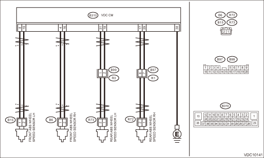
Wiring diagram:
Vehicle dynamics control system Vehicle Dynamics Control System > WIRING DIAGRAM">

| STEP | CHECK | YES | NO |
1.CHECK POOR CONTACT OF CONNECTOR.
Check if there is poor contact between VDCCM&H/U and ABS wheel speed sensor.
Is there poor contact?
Repair the connector.
Diagnostic Procedure with Diagnostic Trouble Code (DTC) > DTC C1241 REAR LEFT ABS SENSOR CIRCUIT">Go to Step 2.
2.CHECK HARNESS CONNECTOR BETWEEN VDCCM&H/U AND ABS WHEEL SPEED SENSOR (CHECK FOR OPEN CIRCUIT).
1) Turn the ignition switch to OFF.
2) Disconnect the connector (B310) from the VDCCM&H/U.
3) Disconnect the connector from ABS wheel speed sensor.
4) Measure the resistance between VDCCM&H/U connector and ABS wheel speed sensor connector.
Connector & terminal
DTC C1211
(B310) No. 4 — (B6) No. 1:
(B310) No. 16 — (B6) No. 2:
DTC C1221
(B310) No. 8 — (B15) No. 1:
(B310) No. 19 — (B15) No. 2:
DTC C1231
(B310) No. 29 — (R72) No. 1:
(B310) No. 17 — (R72) No. 2:
DTC C1241
(B310) No. 18 — (R73) No. 1:
(B310) No. 31 — (R73) No. 2:
Is the resistance less than 1 ??
Diagnostic Procedure with Diagnostic Trouble Code (DTC) > DTC C1241 REAR LEFT ABS SENSOR CIRCUIT">Go to Step 3.
Repair the harness connector between VDCCM&H/U and ABS wheel speed sensor.
3.CHECK GROUND SHORT OF HARNESS.
Measure the resistance between VDCCM&H/U connector and chassis ground.
Connector & terminal
DTC C1211
(B310) No. 4 — Chassis ground:
DTC C1221
(B310) No. 8 — Chassis ground:
DTC C1231
(B310) No. 29 — Chassis ground:
DTC C1241
(B310) No. 18 — Chassis ground:
Is the resistance 1 M? or more?
Diagnostic Procedure with Diagnostic Trouble Code (DTC) > DTC C1241 REAR LEFT ABS SENSOR CIRCUIT">Go to Step 4.
Repair the harness connector between VDCCM&H/U and ABS wheel speed sensor.
4.CHECK ABS WHEEL SPEED SENSOR POWER SUPPLY CIRCUIT.
1) Connect the VDCCM&H/U connector.
2) Turn the ignition switch to ON.
3) Measure the voltage between ABS wheel speed sensor connector and chassis ground.
Connector & terminal
DTC C1211
(B6) No. 2 (+) — Chassis ground (−):
DTC C1221
(B15) No. 2 (+) — Chassis ground (−):
DTC C1231
(R72) No. 2 (+) — Chassis ground (−):
DTC C1241
(R73) No. 2 (+) — Chassis ground (−):
Is the voltage 5 — 16 V?
Diagnostic Procedure with Diagnostic Trouble Code (DTC) > DTC C1241 REAR LEFT ABS SENSOR CIRCUIT">Go to Step 6.
Diagnostic Procedure with Diagnostic Trouble Code (DTC) > DTC C1241 REAR LEFT ABS SENSOR CIRCUIT">Go to Step 5.
5.CHECK VDCCM&H/U POWER SUPPLY CIRCUIT.
1) Turn the ignition switch to OFF.
2) Disconnect the VDCCM&H/U connector.
3) Turn the ignition switch to ON.
4) Measure the voltage between VDCCM&H/U connector terminals.
Connector & terminal
(B310) No. 1 (+) — (B310) No. 38 (−):
(B310) No. 25 (+) — (B310) No. 38 (−):
(B310) No. 28 (+) — (B310) No. 38 (−):
Is the voltage 10 — 15 V?
Diagnostic Procedure with Diagnostic Trouble Code (DTC) > DTC C1241 REAR LEFT ABS SENSOR CIRCUIT">Go to Step 6.
Check the generator, battery and VDCCM&H/U power supply circuit.
6.CHECK ABS WHEEL SPEED SENSOR SIGNAL.
1) Prepare an oscilloscope.
2) Check the ABS wheel speed sensor. Front ABS Wheel Speed Sensor > INSPECTION"> Rear ABS Wheel Speed Sensor > INSPECTION">
Is the pattern the same waveform as shown in the figure?
Diagnostic Procedure with Diagnostic Trouble Code (DTC) > DTC C1241 REAR LEFT ABS SENSOR CIRCUIT">Go to Step 7.
Replace the ABS wheel speed sensor. Front ABS Wheel Speed Sensor"> Rear ABS Wheel Speed Sensor">
7.CHECK VDCCM&H/U.
1) Connect all connectors.
2) Perform the Clear Memory Mode. Clear Memory Mode">
3) Perform the Inspection Mode. Inspection Mode">
4) Read the DTC. Read Diagnostic Trouble Code (DTC)">
Is the same DTC displayed?
Replace the VDCCM only. VDC Control Module and Hydraulic Control Unit (VDCCM&H/U) > REPLACEMENT">
Diagnostic Procedure with Diagnostic Trouble Code (DTC) > DTC C1241 REAR LEFT ABS SENSOR CIRCUIT">Go to Step 8.
8.CHECK DETECTION OF OTHER DTCS FOR VDC.
Read Diagnostic Trouble Code (DTC)">
Is any other DTC displayed?
Perform the diagnosis according to DTC. List of Diagnostic Trouble Code (DTC)">
Currently, it is normal. There may have been a temporary poor contact in the harness and connector or a temporary noise interference.
 Dtc c1232 rear right abs sensor signal
VEHICLE DYNAMICS CONTROL (VDC) (DIAGNOSTICS) > Diagnostic Procedure with Diagnostic Trouble Code (DTC)DTC C1232 REAR RIGHT ABS SENSOR SIGNALNOTE:For the diagnostic procedure, refer to “DTC C1 ...
 Dtc c1242 rear left abs sensor signal
VEHICLE DYNAMICS CONTROL (VDC) (DIAGNOSTICS) > Diagnostic Procedure with Diagnostic Trouble Code (DTC)DTC C1242 REAR LEFT ABS SENSOR SIGNALDTC detecting condition:• Defective ABS wheel speed ...
Other materials:
Fuel gauge
Fuel gauge (type A)
Trip knob
Fuel gauge (type B)
Trip knob (U.S.-spec. models)
Trip knob (except U.S.-spec. models)
The fuel gauge is displayed when the
ignition is in the "ON" position, and it
shows the approximate amount of fuel
remaining in the tank.
The gauge indic ...
Installation
CONTROL SYSTEMS > AT Shift Lock Solenoid and “P” Range SwitchINSTALLATIONInstall in the reverse order of removal.NOTE:Insert the solenoid unit terminals to the harness connector.(A)Solenoid unit (color code: blue)(B)Solenoid unit (color code: black) ...
General diagnostic table Inspection
DRIVE SHAFT SYSTEM > General Diagnostic TableINSPECTIONNOTE:Vibration while cruising may be caused by an unbalanced tire, improper tire inflation pressure, improper wheel alignment, etc.SymptomsPossible causeCorrective actionNoise or vibration from propeller shaft• Center bearing• Run ...
