Subaru Crosstrek Service Manual: Dtc c0071 steer angle sensor op
VEHICLE DYNAMICS CONTROL (VDC) (DIAGNOSTICS) > Diagnostic Procedure with Diagnostic Trouble Code (DTC)
DTC C0071 STEER ANGLE SENSOR OP
DTC detecting condition:
Steering angle sensor output is faulty.
Trouble symptom:
• VDC does not operate.
• EyeSight does not operate.
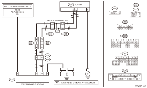
Wiring diagram:
Vehicle dynamics control system Vehicle Dynamics Control System > WIRING DIAGRAM">
| STEP | CHECK | YES | NO |
1.CHECK POWER SUPPLY FOR STEERING ANGLE SENSOR.
1) Turn the ignition switch to OFF.
2) Disconnect the connector from steering angle sensor.
3) Turn the ignition switch to ON.
4) Measure the voltage between steering angle sensor and chassis ground.
Connector & terminal
(B231) No. 4 (+) — Chassis ground (−):
Is the voltage 10 — 15 V?
Diagnostic Procedure with Diagnostic Trouble Code (DTC) > DTC C0071 STEER ANGLE SENSOR OP">Go to Step 2.
Repair the steering angle sensor power supply circuit including the fuse.
2.CHECK GROUND CIRCUIT OF STEERING ANGLE SENSOR (CHECK FOR OPEN CIRCUIT).
Measure the resistance between steering angle sensor and chassis ground.
Connector & terminal
(B231) No. 1 — Chassis ground:
Is the resistance less than 10 ??
Diagnostic Procedure with Diagnostic Trouble Code (DTC) > DTC C0071 STEER ANGLE SENSOR OP">Go to Step 3.
Repair ground circuit in the steering angle sensor.
3.CHECK STEERING ANGLE SENSOR HARNESS (CHECK FOR OPEN CIRCUIT).
1) Disconnect the connector from the VDCCM&H/U.
2) Measure the resistance between VDCCM&H/U and steering angel sensor.
Connector & terminal
(B231) No. 2 — (B310) No. 21:
(B231) No. 3 — (B310) No. 23:
Is the resistance less than 1 ??
Diagnostic Procedure with Diagnostic Trouble Code (DTC) > DTC C0071 STEER ANGLE SENSOR OP">Go to Step 4.
Repair the harness between the steering angle sensor and VDCCM&H/U.
4.CHECK GROUND SHORT CIRCUIT OF STEERING ANGLE SENSOR HARNESS.
Measure the resistance between steering angle sensor and chassis ground.
Connector & terminal
(B231) No. 2 — Chassis ground:
(B231) No. 3 — Chassis ground:
Is the resistance 10 ? or more?
Diagnostic Procedure with Diagnostic Trouble Code (DTC) > DTC C0071 STEER ANGLE SENSOR OP">Go to Step 5.
Repair the harness between the steering angle sensor and VDCCM&H/U.
5.CHECK STEERING WHEEL.
1) Drive the vehicle on a flat road.
2) Park the vehicle straight.
3) Check the steering wheel for deviation from center.
Is the deviation from the center of steering wheel less than 5°?
Diagnostic Procedure with Diagnostic Trouble Code (DTC) > DTC C0071 STEER ANGLE SENSOR OP">Go to Step 6.
Perform the centering adjustment of steering wheel, and perform Set up mode for Neutral of Steering Angle Sensor & Lateral G Sensor 0 point. VDC Control Module and Hydraulic Control Unit (VDCCM&H/U) > ADJUSTMENT">
6.CHECK OUTPUT OF STEERING ANGLE SENSOR USING SUBARU SELECT MONITOR.
1) Adjust steering wheel to the center position.
2) Using the Subaru Select Monitor, select “Data monitor”. Subaru Select Monitor > OPERATION">
3) Read the «Steer Angle Sensor Op» displayed on display.
Is the reading of «Steer Angle Sensor Op» −10° — 10°?
Perform Set up mode for Neutral of Steering Angle Sensor & Lateral G Sensor 0 point. VDC Control Module and Hydraulic Control Unit (VDCCM&H/U) > ADJUSTMENT">
Diagnostic Procedure with Diagnostic Trouble Code (DTC) > DTC C0071 STEER ANGLE SENSOR OP">Go to Step 7.
Check the installation of the steering wheel and steering angle sensor.
7.CHECK VDCCM&H/U.
1) Turn the ignition switch to OFF.
2) Connect all connectors.
3) Perform the Clear Memory Mode. Clear Memory Mode">
4) Perform the Inspection Mode. Inspection Mode">
5) Read the DTC. Read Diagnostic Trouble Code (DTC)">
Is the same DTC displayed?
Replace the steering angle sensor. Steering Angle Sensor">
Diagnostic Procedure with Diagnostic Trouble Code (DTC) > DTC C0071 STEER ANGLE SENSOR OP">Go to Step 8.
8.CHECK DETECTION OF OTHER DTCS FOR VDC.
Read Diagnostic Trouble Code (DTC)">
Is any other DTC displayed?
Perform the diagnosis according to DTC. List of Diagnostic Trouble Code (DTC)">
Currently, it is normal. There may have been a temporary poor contact in the harness and connector or a temporary noise interference.
 Dtc c0081 system failure
VEHICLE DYNAMICS CONTROL (VDC) (DIAGNOSTICS) > Diagnostic Procedure with Diagnostic Trouble Code (DTC)DTC C0081 SYSTEM FAILUREDTC detecting condition:VDC long time sequential controlTrouble symptom ...
 Dtc c0072 abnormal yaw rate sensor output
VEHICLE DYNAMICS CONTROL (VDC) (DIAGNOSTICS) > Diagnostic Procedure with Diagnostic Trouble Code (DTC)DTC C0072 ABNORMAL YAW RATE SENSOR OUTPUTDTC DETECTING CONDITION:Defective yaw rate sensorTROUB ...
Other materials:
Interior light off delay timer setting
1. Perform the preparation steps according
to "Preparation for car settings"
2. Operate the " " or "
" switch to
select the "Interior Light" item. Then push
the button.
3. The current setting will be displayed.
Push the button to enter the
selection
mode.
4. Select ...
A/c filter Replacement
HVAC SYSTEM (HEATER, VENTILATOR AND A/C) > A/C FilterREPLACEMENT1. Remove the pocket assembly.(1) Attach the protective tape (a) to the panel center LWR.(2) Remove the damper COMPL - pocket.(3) Release the stoppers and remove the pocket assembly by pulling it toward you.2. Pinch the tabs to relea ...
Dtc b1570 antenna
IMMOBILIZER (DIAGNOSTICS) > Diagnostic Procedure with Diagnostic Trouble Code (DTC)DTC B1570 ANTENNADTC detecting condition:Faulty antennaCAUTION:When the body integrated unit is replaced, registration of the immobilizer system is required. For details, refer to the “REGISTRATION MANUAL FOR ...
