Subaru Crosstrek Service Manual: Dtc b2814 power supply low voltage
EyeSight (DIAGNOSTICS) > Diagnostic Procedure with Diagnostic Trouble Code (DTC)
DTC B2814 POWER SUPPLY LOW VOLTAGE
Detected when the status of 7.0 V or less continues approximately for 5 seconds and is judged to be low-voltage malfunction, or when the +B harness of the stereo camera is broken.
DTC DETECTING CONDITION:
• Input voltage to stereo camera is out of specifications.
• Defective stereo camera control harness (open circuit in +B harness)
• Defective stereo camera
TROUBLE SYMPTOM:
• All functions of EyeSight system do not operate.
• EyeSight warning light blinks or illuminates.
• Cruise indicator light blinks.
• Malfunction indicator light illuminates.
• VDC warning light illuminates.
• ATF temperature warning light illuminates.
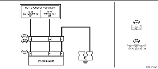
WIRING DIAGRAM:
EyeSight System EyeSight System > WIRING DIAGRAM">
| STEP | CHECK | YES | NO |
1.CHECK GENERATOR.
1) Start the engine and idle for a while.
2) Measure the voltage between generator terminal B and chassis ground.
Connector & terminal
Generator terminal B (+) — Chassis ground (−):
Is the voltage 10 V or more?
Diagnostic Procedure with Diagnostic Trouble Code (DTC) > DTC B2814 POWER SUPPLY LOW VOLTAGE">Go to Step 2.
Check the generator. Generator">
2.CHECK BATTERY TERMINAL.
Turn the ignition switch to OFF.
Is the battery terminal connected securely?
Diagnostic Procedure with Diagnostic Trouble Code (DTC) > DTC B2814 POWER SUPPLY LOW VOLTAGE">Go to Step 3.
Tighten the battery terminal securely.
3.CHECK FUSE.
Check fuses No. 7 and No. 12 in the fuse & relay box. Relay and Fuse">
Is the fuse OK?
Diagnostic Procedure with Diagnostic Trouble Code (DTC) > DTC B2814 POWER SUPPLY LOW VOLTAGE">Go to Step 4.
Replace the faulty fuse. When the replaced fuse blows out easily, check the short circuit in harness.
4.CHECK HARNESS (POWER SUPPLY CIRCUIT).
1) Disconnect the stereo camera.
2) Turn the ignition switch to ON.
3) Measure the voltage between harness connector of stereo camera and chassis ground.
Connector & terminal
(R137) No. 6 (+) — Chassis ground (−):
(R137) No. 8 (+) — Chassis ground (−):
Is the voltage 10 V or more?
Diagnostic Procedure with Diagnostic Trouble Code (DTC) > DTC B2814 POWER SUPPLY LOW VOLTAGE">Go to Step 5.
Check the power supply system circuit, and if any fault is found, repair the defective parts or replace the harness.
5.CHECK HARNESS (GROUND CIRCUIT).
1) Turn the ignition switch to OFF.
2) Disconnect the ground cable from battery.
3) Measure the resistance between stereo camera and chassis ground.
Connector & terminal
(R137) No. 7 — Chassis ground:
Is the resistance less than 10 ??
Diagnostic Procedure with Diagnostic Trouble Code (DTC) > DTC B2814 POWER SUPPLY LOW VOLTAGE">Go to Step 6.
Check the ground system circuit, and if any fault is found, repair the defective parts or replace the harness.
6.CHECK POOR CONTACT OF CONNECTORS.
Check stereo camera connector.
Is there poor contact of the connector?
Repair the connector.
Diagnostic Procedure with Diagnostic Trouble Code (DTC) > DTC B2814 POWER SUPPLY LOW VOLTAGE">Go to Step 7.
7.CHECK STEREO CAMERA.
1) Connect all connectors and battery terminals securely.
2) Start the engine, drive the vehicle at 40 km/h (24.9 MPH) or more, stop the vehicle and then stop the engine.
3) After 3 seconds or more have elapsed, restart the engine.
4) Clear the memory. Clear Memory Mode">
5) Read the DTC. Diagnostic Code(s) Display">
Is the same DTC (DTC B2814 or B2815) displayed?
Replace the stereo camera. Stereo Camera > REMOVAL">
Even if DTC is displayed, the circuit has returned to a normal condition at this time. Reproduce the failure, and then perform the diagnosis again.
NOTE:
In this case, temporary poor contact of connector, or temporary open or short circuit of harness may be the cause.
 Dtc b2810 incompatible with eyesight (combination meter)
EyeSight (DIAGNOSTICS) > Diagnostic Procedure with Diagnostic Trouble Code (DTC)DTC B2810 INCOMPATIBLE WITH EyeSight (COMBINATION METER)Detected when the combination meter, which is not designed ex ...
 Dtc b2815 power supply high voltage
EyeSight (DIAGNOSTICS) > Diagnostic Procedure with Diagnostic Trouble Code (DTC)DTC B2815 POWER SUPPLY HIGH VOLTAGEDetected when the status for the battery voltage of 16 V or more continues approxi ...
Other materials:
Inspection
SPEED CONTROL SYSTEMS(H4DO) > Accelerator PedalINSPECTION1. CHECK ACCELERATOR PEDAL SENSOR AREA (METHOD WITH CIRCUIT TESTER)1. Remove the glove box. Glove Box > REMOVAL">2. Turn the ignition switch to ON. (Engine OFF)3. Measure the voltage between ECM connector terminals.• Main ...
Dtc b1623 side airbag sensor rh initialization error
AIRBAG SYSTEM (DIAGNOSTICS) > Diagnostic Chart with Trouble CodeDTC B1623 SIDE AIRBAG SENSOR RH INITIALIZATION ERRORDiagnosis start condition:Ignition voltage is 10 V to 16 V.DTC detecting condition:• Open or short circuit in harness of side sensor bus (RH)• Side airbag sensor (RH) an ...
Replacement
CONTINUOUSLY VARIABLE TRANSMISSION(TR580) > Differential Gear OilREPLACEMENTCAUTION:• Immediately after the vehicle has been running or after idling for a long time, the differential gear oil will be hot. Be careful not to burn yourself.• Be careful not to spill differential gear oil ...
