Subaru Crosstrek Service Manual: Dtc b1863 short in driver s knee airbag (to +b)
AIRBAG SYSTEM (DIAGNOSTICS) > Diagnostic Chart with Trouble Code
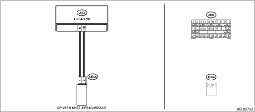
DTC B1863 SHORT IN DRIVER’S KNEE AIRBAG (TO +B)
Diagnosis start condition:
Ignition voltage is 10 V to 16 V.
DTC detecting condition:
• Airbag main harness circuit is shorted to power supply.
• Knee airbag module harness circuit is shorted to power supply.
• Knee airbag module is faulty.
• Airbag control module is faulty.
CAUTION:
Before performing diagnosis, refer to “CAUTION” in “General Description”. General Description > CAUTION">
Wiring diagram:
Airbag system Airbag System > WIRING DIAGRAM">
| STEP | CHECK | YES | NO |
1.CHECK POOR CONTACT OF CONNECTORS.
Check for poor contact of the connectors between the airbag control module and the knee airbag module.
Is there poor contact?
Replace the airbag harness.
Diagnostic Chart with Trouble Code > DTC B1863 SHORT IN DRIVER’S KNEE AIRBAG (TO +B)">Go to Step 2.
2.CHECK KNEE AIRBAG MODULE.
1) Turn the ignition switch to OFF, disconnect the battery ground cable, and wait for 60 seconds or more.
2) Disconnect the connector (AB66) from knee airbag module.
3) Connect the connector (1N) in the test harness N to the connector (AB66).
4) Connect the airbag resistor to the connector (2N) of test harness N.
5) Connect the battery ground terminal and turn the ignition switch to ON.
Does the airbag warning light illuminate for six seconds and go off?
Replace the knee airbag module. Knee Airbag Module > REMOVAL">
Diagnostic Chart with Trouble Code > DTC B1863 SHORT IN DRIVER’S KNEE AIRBAG (TO +B)">Go to Step 3.
3.CHECK AIRBAG MAIN HARNESS (KNEE AIRBAG HARNESS).
1) Turn the ignition switch to OFF, disconnect the battery ground cable, and wait for 60 seconds or more.
2) Disconnect the airbag resistor from test harness N.
3) Remove the instrument panel lower cover and column cover, and disconnect the connector (AB7) from (AB2).
4) Remove the console front panel and disconnect the connector (AB9).
5) Disconnect the connectors (AB6, AB17, AB18) from the airbag control module, and connect the connector (1AG) in the test harness AG.
6) Connect the battery ground terminal and turn the ignition switch to ON.
7) Measure the voltage between connector (3AG) in the test harness AG and chassis ground.
Connector & terminal
(3AG) No. 14 (+) — Chassis ground (–):
(3AG) No. 16 (+) — Chassis ground (–):
Is the voltage less than 1 V?
Diagnostic Chart with Trouble Code > DTC B1863 SHORT IN DRIVER’S KNEE AIRBAG (TO +B)">Go to Step 4.
Replace the airbag main harness along with body harness.
4.CHECK AIRBAG CONTROL MODULE.
1) Connect all connectors.
2) Clear the memory. Clear Memory Mode">
3) Perform the Inspection Mode. Inspection Mode">
4) Read the DTC. (Current malfunction) Read Diagnostic Trouble Code (DTC)">
Is DTC B1863 displayed?
Replace the airbag control module. Airbag Control Module">
Diagnostic Chart with Trouble Code > DTC B1863 SHORT IN DRIVER’S KNEE AIRBAG (TO +B)">Go to Step 5.
5.CHECK FOR ANY OTHER DTC ON DISPLAY.
Is any other DTC displayed?
Check DTC using “List of Diagnostic Trouble Code (DTC)”. List of Diagnostic Trouble Code (DTC)">
Finish the diagnosis.
 Dtc b1862 short in driver s knee airbag (to ground)
AIRBAG SYSTEM (DIAGNOSTICS) > Diagnostic Chart with Trouble CodeDTC B1862 SHORT IN DRIVER’S KNEE AIRBAG (TO GROUND)Diagnosis start condition:Ignition voltage is 10 V to 16 V.DTC detecting con ...
 Dtc b1900 short in front p/t rh
AIRBAG SYSTEM (DIAGNOSTICS) > Diagnostic Chart with Trouble CodeDTC B1900 SHORT IN FRONT P/T RHDiagnosis start condition:Ignition voltage is 10 V to 16 V.DTC detecting condition:• Seat belt p ...
Other materials:
Removal
CONTINUOUSLY VARIABLE TRANSMISSION(TR580) > Inhibitor SwitchREMOVAL1. Shift the select lever to “N” range.2. Disconnect the ground cable from battery. NOTE">NOTE:For model with battery sensor, disconnect the ground terminal from battery sensor.3. Lift up the vehicle.4. Remove ...
Dtc c1212 front right abs sensor signal
VEHICLE DYNAMICS CONTROL (VDC) (DIAGNOSTICS) > Diagnostic Procedure with Diagnostic Trouble Code (DTC)DTC C1212 FRONT RIGHT ABS SENSOR SIGNALNOTE:For the diagnostic procedure, refer to “DTC C1242 REAR LEFT ABS SENSOR SIGNAL”. Diagnostic Procedure with Diagnostic Trouble Code (DTC) &g ...
43
CRUISE CONTROL SYSTEM (DIAGNOSTICS) > Diagnostic Procedure with Cancel Code43• The situation that some or all functions for ABS/VDC can not work is detected.During cruise driving or cruise setting, the situation that some or all functions for ABS/VDC can not work is detected. Basic Diagnost ...
