Subaru Crosstrek Service Manual: Disassembly
DIFFERENTIALS > Rear Differential (VA-type)
DISASSEMBLY
To detect the real cause of trouble, inspect the following items before disassembling.
• Tooth contact and backlash between hypoid driven gear and drive pinion
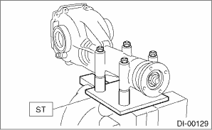
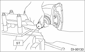
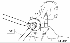
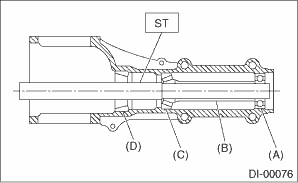
1. Set the ST on vise and install the differential assembly to ST.
| ST 398217700 | ATTACHMENT SET |
2. Remove the drain plug and filler plug.
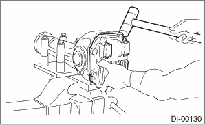
3. Remove the rear cover by removing retaining bolts.
NOTE:
Remove it by tapping with a plastic hammer.
4. Remove the stud bolts from rear cover if necessary.
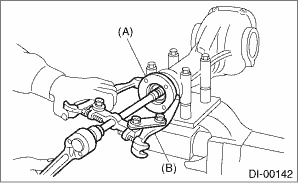
5. Remove the air breather cap.
NOTE:
• Do not attempt to remove the air breather cap unless necessary.
• Whenever the air breather cap is removed, replace it with a new part.
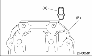
(A) | Air breather cap |
(B) | Rear cover |
6. Remove the lock plate RH and LH.
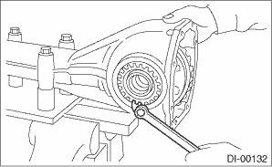
7. Remove the side retainer RH and LH with ST.
NOTE:
When keeping the retainers aside, use labels etc. to avoid confusing the left and right.
| ST 18630AA010 | WRENCH COMPL RETAINER |
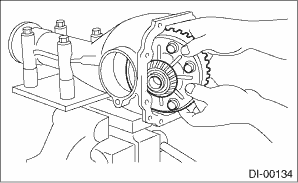
8. Pull out the differential case assembly from differential carrier.
NOTE:
Be careful not to hit the teeth of hypoid driven gear against the differential carrier.
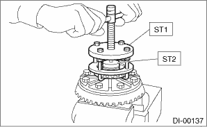
9. Remove the bearing race from side retainer RH and LH with ST1 and ST2.
| ST1 499705401 | PULLER ASSY |
| ST2 499705404 | SEAT |
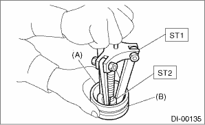
(A) | Bearing race |
(B) | Side retainer |
10. Remove the oil seal from RH and LH side retainers.
NOTE:
Perform this operation only when changing oil seal.
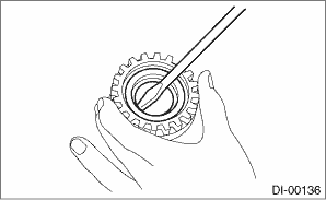
11. Remove the O-rings.
12. Remove the side bearing cone with ST1 and ST2.
NOTE:
• Do not attempt to disassemble the parts unless necessary.
• Set the puller so that its claws catch the edge of the side bearing cone.
• Store so that the right and left side bearing races and cones are not mixed together.
| ST1 899524100 | PULLER SET |
| ST2 399520105 | SEAT |
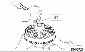
13. Using the ST, loosen the hypoid driven gear bolt and remove the hypoid driven gear.
| ST 18270KA020 | SOCKET (E20) |
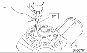
14. Remove the spring pin from hypoid driven gear side using ST.
| ST 899904100 | STRAIGHT PIN REMOVER |
15. Draw out the pinion mate shaft and remove pinion mate gears, side gears and side gear thrust washers.
NOTE:
The gears and washers should be marked with RH or LH, front or rear, or kept separately.
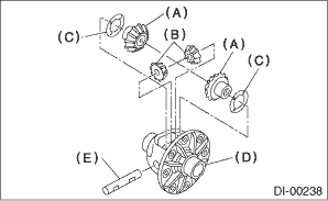
(A) | Side gear |
(B) | Pinion mate gear |
(C) | Side gear thrust washer |
(D) | Differential case |
(E) | Pinion mate shaft |
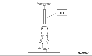
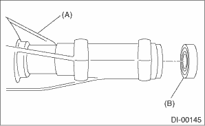
16. Remove the self-locking nut while securing the companion flange with ST.
| ST 498427200 | FLANGE WRENCH |
17. Extract the companion flange with a puller.
(A) | Companion flange |
(B) | Puller |
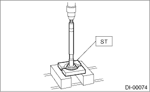
18. Press the end of drive pinion shaft using ST and remove the rear bearing cone, pinion height adjusting washer, preload adjusting spacer and washer.
NOTE:
Hold the drive pinion so as not to drop it.
| ST 398467700 | DRIFT |
19. Remove the rear bearing cone from drive pinion by supporting the bearing cone with ST.
NOTE:
Place the remover so that its center-recessed side faces the bearing cone.
| ST 498515500 | REMOVER |
20. Remove the front oil seal from differential carrier using ST.
| ST 398527700 | PULLER ASSY |
(A) | Differential carrier |
(B) | Front oil seal |
21. Remove the pilot bearing together with the front bearing cone and spacer using the ST.
| ST 398467700 | DRIFT |
(A) | Pilot bearing |
(B) | Spacer |
(C) | Front bearing |
(D) | Rear bearing race |
22. When replacing the bearings, tap out the front bearing race and rear bearing race in this order using a brass bar to remove them.
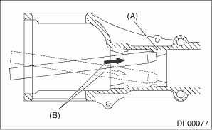
(A) | 2 cutout portions along diagonal lines |
(B) | Tap alternately with brass bar. |
 Assembly
DIFFERENTIALS > Rear Differential (VA-type)ASSEMBLYNOTE:• Assemble in the reverse order of disassembly.• Check and adjust each part during assembly.• Keep the shims and washers in ...
 Inspection
DIFFERENTIALS > Rear Differential (VA-type)INSPECTIONWash all the disassembled parts clean, and examine them for wear, damage or other defects. Repair or replace the defective parts as necessary.1. ...
Other materials:
Access key - if access key does not operate properly
CAUTION
Keep metallic objects, magnetic
sources and signal transmitters
away from the area between the
access key and the push-button
ignition switch. They may interfere
with the communication between
the access key and the push-button
ignition switch.
The following functions may be inopera ...
Dtc c0024 front left abs sensor signal
VEHICLE DYNAMICS CONTROL (VDC) (DIAGNOSTICS) > Diagnostic Procedure with Diagnostic Trouble Code (DTC)DTC C0024 FRONT LEFT ABS SENSOR SIGNALNOTE:For the diagnostic procedure, refer to “DTC C0028 REAR LEFT ABS SENSOR SIGNAL”. Diagnostic Procedure with Diagnostic Trouble Code (DTC) > ...
Basic diagnostic procedure Procedure
AIRBAG SYSTEM (DIAGNOSTICS) > Basic Diagnostic ProcedurePROCEDURESTEPCHECKYESNO1.CHECK WARNING LIGHT.Check whether the airbag warning light in the combination meter is lit.Does the airbag warning light illuminate? Basic Diagnostic Procedure > PROCEDURE">Go to Step 2.Perform the diagnos ...
