Subaru Crosstrek Service Manual: Caution
LAN SYSTEM (DIAGNOSTICS) > General Description
CAUTION
1. SUPPLEMENTAL RESTRAINT SYSTEM “AIRBAG”
Airbag system wiring harness is routed near the body integrated unit and twisted pair line.
CAUTION:
• Do not use the electrical test equipment on all airbag system wiring harnesses and connectors.
• Be careful not to damage the airbag system wiring harness when servicing the body integrated unit and LAN system.
2. LAN SYSTEM
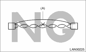
• Bus line of LAN system is twisted pair line. Be careful not to by-pass or partly unbind the twisted pair line.
• Do not make clearance between bus lines (CAN High, CAN Low).
• Difference of bus line length should be within 10 cm (3.94 in).
• Fray near the connector should be within 8 cm (3.14 in).

(A) | Bypass wire connection |
• If the characteristics of the twisted pair line are changed, it may extremely weaken against noise.
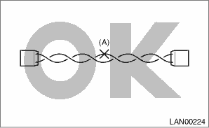
• When repairing the harness, connect the wires using soldering and protect it with insulating tape etc.

(A) | Soldering and protection with insulating tape |
3. TIME STAMP
There are three types of record data for the information of time stamp, and they are stored together with diagnostic codes.
NOTE:
Depending on DTCs, time stamp may not be stored.
(a) «Trip Count»
This indicates the number of times that the ignition has been turned to ON since the vehicle was manufactured. The ignition ON count of when the diagnostic code is stored is displayed on the diagnostic code check screen.
NOTE:
Subaru Select Monitor 4 screen (A/C system diagnostic code and time stamp)
Code | Description & trouble position | Trouble occurrence record | «Trip Count» | «Time Count» | «Category» |
B14E1 | Air mix door actuator stepping motor circuit wire break (driver’s seat) | Detected on the first time | 983 | 18000 | Common |
B14E7 | Heater core rear sensor circuit wire break | Detected on the 2nd time | 984 | 117800 | Common |
The current Trip Count can be checked at “Current Data Display & Save” in “Integ. unit mode”.
By comparing the current Trip Count and the Trip Count of when the diagnostic code was stored, it is possible to determine that it is how many ignition-ON operations ago that DTC was stored.
(b) «Time Count»
The elapsed time from when the ignition is turned to ON to when the diagnostic code is stored is displayed on the diagnostic code check screen. It is possible to determine the length of time that passed between when the user started driving and when the diagnostic code was stored. Therefore, if Trip Count until the vehicle-received-date is determined by interviewing the user, it is possible to estimate where the user was driving when the diagnostic code was stored, using the information such as Trip Count and Time Count. This estimate is useful information to perform diagnosis including checking of repeatability.
NOTE:
Subaru Select Monitor 4 screen (A/C system diagnostic code and time stamp)
Code | Description & trouble position | Trouble occurrence record | «Trip Count» | «Time Count» | «Category» |
B14E1 | Air mix door actuator stepping motor circuit wire break (driver’s seat) | Detected on the first time | 983 | 18000 | Common |
B14E7 | Heater core rear sensor circuit wire break | Detected on the 2nd time | 984 | 117800 | Common |
When multiple diagnostic codes are recorded for one trouble, it is extremely important to determine the diagnostic code that was stored first. (It is important to perform the diagnosis for the first recorded diagnostic code.) In this case, it is also possible to immediately determine which diagnostic code was recorded first, using the information such as Trip Count and Time Count.
(c) «Category»
Each unit individually counts the elapsed time since the ignition is turned to ON. However, these time counts may have some errors, and therefore, the control modules need to be adjusted to the time carried by the master-time unit (the body integrated unit). When the count is set as common, it means that each control module is already adjusted to the master time, and the display for the master integrated unit is always indicated as “Common”. When the count is indicated as “Originally”, it means that the time is not synchronized with the master time. In this case, check the communication between the corresponding control module and integrated unit. When all controls other than the body integrated unit is indicated as “Originally”, perform the basic inspection for the body integrated unit. Basic Diagnostic Procedure > PROCEDURE">
NOTE:
Subaru Select Monitor 4 screen (A/C system diagnostic code and time stamp)
Code | Description & trouble position | Trouble occurrence record | «Trip Count» | «Time Count» | «Category» |
B14E1 | Air mix door actuator stepping motor circuit wire break (driver’s seat) | Detected on the first time | 983 | 18000 | Common |
B14E7 | Heater core rear sensor circuit wire break | Detected on the 2nd time | 984 | 117800 | Common |
Even when multiple diagnostic codes are stored in multiple control modules, it is possible to determine the code stored first through the categorizing feature.
NOTE:
Troubleshooting for CAN system U-code occurrence
When the first stored diagnostic code is a U-code for CAN system, perform the troubleshooting as a U code combination, instead of a U code alone. In addition, when CAN open circuit occurs, communication of the diagnostic device itself becomes impossible beyond the particular areas. However, trouble positions can also be determined by the combination of initial communication success/failure. Thus, by performing the basic diagnostic procedure in LAN system, trouble positions can be determined efficiently on the principle above. Basic Diagnostic Procedure > PROCEDURE">
 Preparation tool
LAN SYSTEM (DIAGNOSTICS) > General DescriptionPREPARATION TOOL1. SPECIAL TOOLILLUSTRATIONTOOL NUMBERDESCRIPTIONREMARKS — SUBARU SELECT MONITOR 4Used for setting of each function and troubleshooti ...
Other materials:
Dtc p0560 system voltage
ENGINE (DIAGNOSTICS)(H4DO) > Diagnostic Procedure with Diagnostic Trouble Code (DTC)DTC P0560 SYSTEM VOLTAGEDTC DETECTING CONDITION:Immediately at fault recognitionCAUTION:After servicing or replacing faulty parts, perform Clear Memory Mode Clear Memory Mode > OPERATION">, and Inspect ...
Dtc c0064 normal closing valve 2 malfunction
VEHICLE DYNAMICS CONTROL (VDC) (DIAGNOSTICS) > Diagnostic Procedure with Diagnostic Trouble Code (DTC)DTC C0064 NORMAL CLOSING VALVE 2 MALFUNCTIONDTC detecting condition:• Defective harness connector• Defective VDCH/U solenoid valveTrouble symptom:• ABS does not operate.• ...
Engine oil
CAUTION
If the level gauge cannot be
pulled out easily, twist the level
gauge right and left, then gently
pull it out. Otherwise, you may be
injured accidentally straining
yourself.
Use only engine oil with the
recommended grade and viscosity.
Be careful not to spill engine oil
...

