Subaru Crosstrek Service Manual: Adjustment
CONTINUOUSLY VARIABLE TRANSMISSION(TR580) > Transfer Clutch
ADJUSTMENT
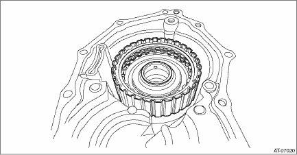
1. Install the transfer clutch assembly to the extension case with the transfer driven gear shims and thrust bearings removed.

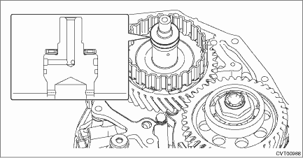
2. Install the thrust bearing to the transfer driven gear.
NOTE:
Make sure to install in the right direction.

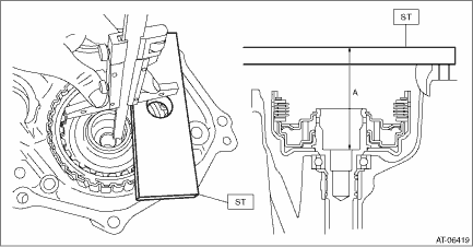
3. Using the ST, measure the height “A” from the ST end face to the thrust bearing catch surface of the transfer clutch assembly.
| ST 499575500 | GAUGE |

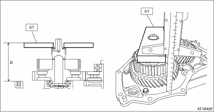
4. Using the ST, measure the height “B” from the transmission case mating surface to the end of ST.
| ST 499575500 | GAUGE |

5. Obtain the thickness of transfer driven gear shim using the following formula to select one to three transfer driven gear shims.
T (mm) = A − B − (0.05 — 0.25)
[T (in) = A − B − (0.002 — 0.01)]
T: Transfer driven gear shim thickness
A: Height from the ST end face to the transfer clutch assembly thrust bearing catch surface
B: Height from the mating surface of the transmission case to the end of the ST
0.05 — 0.25 mm (0.002 — 0.01 in): Clearance
Transfer driven gear shim | |
Part No. | Thickness mm (in) |
33280AA030 | 0.3 (0.012) |
33280AA040 | 0.4 (0.016) |
33280AA050 | 0.5 (0.020) |
 Transfer clutch
...
 Removal
CONTINUOUSLY VARIABLE TRANSMISSION(TR580) > Transfer ClutchREMOVAL1. Remove the transmission assembly from the vehicle. Automatic Transmission Assembly > REMOVAL">2. Remove the extensio ...
Other materials:
Tongue load
Tongue load
Ensure that the trailer tongue load is from
8 to 11 percent of the total trailer weight
and does not exceed the maximum value
of 200 lbs (90 kg).
Jack
Bathroom scale
The tongue load can be weighed with a
bathroom scale as shown in the illustration
above. When weighing ...
Control screen and audio panel
Select to display the audio source
selection screen.
Select to display the play mode
currently selected. Refer to "Select
play mode"
Select to display iPod List. Refer to
"iPod settings"
Shows progress.
Turn to adjust volume.
Press to turn the audio system on/off.
Turn to ...
Dtc b1242 wireless tuner
KEYLESS ACCESS WITH PUSH BUTTON START SYSTEM (DIAGNOSTICS) > Diagnostic Procedure with Diagnostic Trouble Code (DTC)DTC B1242 WIRELESS TUNERDTC detecting condition:When short circuit occurs in harness between keyless access CM and receiver.Trouble symptom:• The keyless access with push butt ...
