Subaru Crosstrek Service Manual: Electrical specification
AIRBAG SYSTEM (DIAGNOSTICS) > Airbag Control Module I/O Signal
ELECTRICAL SPECIFICATION
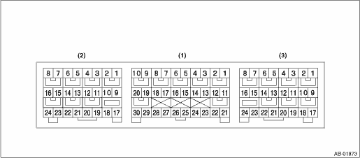
• Terminal numbers in airbag control module connector are shown in the figure.
• The airbag warning light illuminates when the connector is removed from the airbag control module.
Item | Control module terminal No. | ||
Ignition power supply | Dedicated fuse | (1) — 21 | |
Passenger’s airbag module level one | + | (1) — 4 | |
− | (1) — 3 | ||
Passenger’s airbag module level two | + | (1) — 1 | |
− | (1) — 2 | ||
Driver’s airbag module level one | + | (1) — 5 | |
− | (1) — 6 | ||
Driver’s airbag module level two | + | (1) — 8 | |
− | (1) — 7 | ||
Driver’s knee airbag module | + | (1) — 9 | |
− | (1) — 10 | ||
CAN-H | (1) — 13 | ||
CAN-L | (1) — 22 | ||
Collision detection signal | (1) — 24 | ||
Front sub sensor LH | + | (1) — 30 | |
− | (1) — 28 | ||
Front sub sensor RH | + | (1) — 29 | |
− | (1) — 27 | ||
Ground line (GND) | (1) — 25 | ||
(1) — 26 | |||
Passenger’s airbag ON indicator | (1) — 23 | ||
Passenger’s airbag OFF indicator | (1) — 17 | ||
Passenger’s seat belt warning | (1) — 15 | ||
Side airbag sensor LH Curtain airbag sensor LH Front door impact sensor LH | + | (2) — 24 | |
− | (2) — 23 | ||
Seat belt pretensioner LH | + | (2) — 5 | |
− | (2) — 6 | ||
Side airbag module LH | + | (2) — 1 | |
− | (2) — 2 | ||
Curtain airbag module LH | + | (2) — 4 | |
− | (2) — 3 | ||
Occupant detection control module | + | (3) — 16 | |
− | (3) — 24 | ||
Side airbag sensor RH Curtain airbag sensor RH Front door impact sensor RH | + | (3) — 17 | |
− | (3) — 18 | ||
Side airbag module RH | + | (3) — 8 | |
− | (3) — 7 | ||
Curtain airbag module RH | + | (3) — 5 | |
− | (3) — 6 | ||
Seat belt pretensioner RH | + | (3) — 4 | |
− | (3) — 3 | ||
Lap seat belt pretensioner RH | + | (3) — 1 | |
− | (3) — 2 | ||
Satellite safing sensor | + | (3) — 21 | |
− | (3) — 22 | ||

 Wiring diagram
AIRBAG SYSTEM (DIAGNOSTICS) > Airbag Control Module I/O SignalWIRING DIAGRAMRefer to “Airbag System” in WI section. Airbag System > WIRING DIAGRAM"> ...
Other materials:
Dtc c1251 wheel speed sensor system
VEHICLE DYNAMICS CONTROL (VDC) (DIAGNOSTICS) > Diagnostic Procedure with Diagnostic Trouble Code (DTC)DTC C1251 WHEEL SPEED SENSOR SYSTEMNOTE:For the diagnostic procedure, refer to “DTC C1241 REAR LEFT ABS SENSOR CIRCUIT”. Diagnostic Procedure with Diagnostic Trouble Code (DTC) > ...
Preparation tool
CLUTCH SYSTEM > General DescriptionPREPARATION TOOL1. SPECIAL TOOLILLUSTRATIONTOOL NUMBERDESCRIPTIONREMARKS498497100CRANKSHAFT STOPPERUsed for stopping rotation of the flywheel.499747100CLUTCH DISC GUIDEUsed for installing the clutch disc to the flywheel. — SUBARU SELECT MONITOR 4Used for setti ...
Installation
MANUAL TRANSMISSION AND DIFFERENTIAL(5MT) > Transfer Case and Extension Case AssemblyINSTALLATION1. Clean the mating surfaces of the transmission case, transfer case and extension case.2. Apply a coat of grease to the taper roller bearing (transfer case side) of transfer driven gear and the rolle ...
