Subaru Crosstrek Service Manual: Installation
MANUAL TRANSMISSION AND DIFFERENTIAL(5MT) > Transfer Case and Extension Case Assembly
INSTALLATION
1. Clean the mating surfaces of the transmission case, transfer case and extension case.
2. Apply a coat of grease to the taper roller bearing (transfer case side) of transfer driven gear and the roller rolling surface of the taper roller bearing (extension case side).
Grease:
NICHIMOLY N-130 or equivalent
3. Install the center differential and the transfer driven gear.
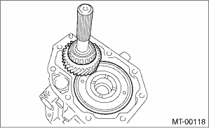
4. Install the taper roller bearing (extension case side) outer race to the transfer driven gear.
5. While pressing the taper roller bearing (extension case side) outer race horizontally, rotate the transfer driven gear for ten turns.
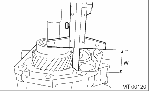
6. Measure the height “W” between transfer case and taper roller bearing (transfer case side) on the transfer driven gear.
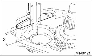
7. Measure the depth “X” of taper roller bearing insertion part of the extension case.
NOTE:
Measure while the taper roller bearing (extension case side) outer race, dish plate and adjusting washer are removed.
8. Calculate the adjusting washer thickness “t” using the following calculation.
t = X − W − (1.715 — 1.765 mm (0.686 — 0.706 in))
X: Depth of taper roller bearing insertion part of extension case
W: Height between transfer case and taper roller bearing (transfer case side) on transfer driven gear
9. Select the adjusting washer with the nearest value in the following table.
Adjusting washer (61 ? 50 ? t) | |
Part No. | Thickness mm (in) |
803050060 | 0.50 (0.0197) |
803050061 | 0.55 (0.0217) |
803050062 | 0.60 (0.0236) |
803050063 | 0.65 (0.0256) |
803050064 | 0.70 (0.0276) |
803050065 | 0.75 (0.0295) |
803050066 | 0.80 (0.0315) |
803050067 | 0.85 (0.0335) |
803050068 | 0.90 (0.0354) |
803050069 | 0.95 (0.0374) |
803050070 | 1.00 (0.0394) |
803050071 | 1.05 (0.0413) |
803050072 | 1.10 (0.0433) |
803050073 | 1.15 (0.0453) |
803050074 | 1.20 (0.0472) |
803050075 | 1.25 (0.0492) |
803050076 | 1.30 (0.0512) |
803050077 | 1.35 (0.0531) |
803050078 | 1.40 (0.0551) |
803050079 | 1.45 (0.0571) |
10. Install the selected adjusting washer, dish plate and taper roller bearing (extension case side) outer race.
NOTE:
Make sure the dish plate is installed in the proper direction.
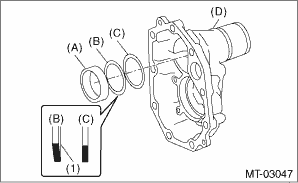
(A) | Taper roller bearing (extension case side) outer race |
(B) | Dish plate |
(C) | Adjusting washer |
(D) | Extension case |
(1) | Paint side |
11. Measure the depth “S” between the transfer case + ST and the center differential.
| ST 398643600 | GAUGE |
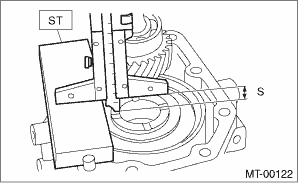
12. Measure the height “T” between the extension case + ST and the transfer drive gear.
| ST 398643600 | GAUGE |
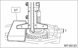
13. Calculate the adjusting washer thickness “U” using the following calculation.
U = S + T − 30 mm (1.18 in) − (0.15 — 0.35 mm (0.0059 — 0.0138 in))
S: Depth between the transfer case + ST and the center differential
T: Height between the extension case + ST and the transfer drive gear
30 mm (1.18 in): Thickness of ST (? 2 pieces)
0.15 — 0.35 mm (0.0059 — 0.0138 in): Clearance
14. Select a suitable adjusting washer in the following table.
Clearance:
0.15 — 0.35 mm (0.0059 — 0.0138 in)
Adjusting washer | |
Part No. | Thickness mm (in) |
803036050 | 0.9 (0.035) |
803036054 | 1.0 (0.039) |
803036051 | 1.1 (0.043) |
803036055 | 1.2 (0.047) |
803036052 | 1.3 (0.051) |
803036056 | 1.4 (0.055) |
803036053 | 1.5 (0.059) |
803036057 | 1.6 (0.063) |
803036058 | 1.7 (0.067) |
803036080 | 1.8 (0.071) |
803036081 | 1.9 (0.075) |
15. Install the adjusting washer to center differential.
16. Apply an appropriate amount of liquid gasket.
Liquid gasket:
THREE BOND 1215B or equivalent
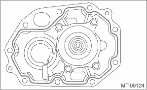
17. Install the extension case assembly.
Tightening torque:
40 N·m (4.1 kgf-m, 29.5 ft-lb)
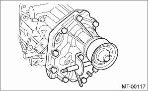
18. Install the shifter arm.
NOTE:
Apply transmission gear oil to the oil seal lips.
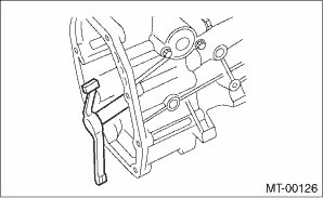
19. Attach the gasket.
NOTE:
Use a new gasket.
20. Hang the shifter arm on 3rd-4th fork rod.
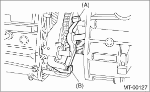
(A) | Shifter arm |
(B) | 3rd-4th fork rod |
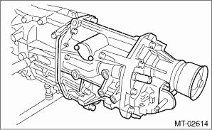
21. Install the transfer case together with the extension case assembly.
Tightening torque:
24.5 N·m (2.5 kgf-m, 18.1 ft-lb)
22. Install the back-up light switch and the neutral position switch. Switches and Harness > INSTALLATION">
23. Install the manual transmission assembly to the vehicle. Manual Transmission Assembly > INSTALLATION">
 Disassembly
MANUAL TRANSMISSION AND DIFFERENTIAL(5MT) > Transfer Case and Extension Case AssemblyDISASSEMBLY1. TRANSFER CASE1. Remove the reverse check sleeve assembly. Reverse Check Sleeve > REMOVAL" ...
Other materials:
Inspection
PERIODIC MAINTENANCE SERVICES > Engine CoolantINSPECTIONCAUTION:• Do not use water instead of coolant.• Refer to “RM” section for the recommended engine coolant. 1. Park the vehicle on a level surface.2. Make sure the engine coolant level in the reservoir tank is between & ...
Wiring diagram
CONTROL SYSTEMS > AT Shift Lock Control SystemWIRING DIAGRAM1. MODEL WITHOUT PUSH BUTTON IGNITION SWITCH(1)Ignition switch(5)TCM (shift range information)(9)Battery(2)Stop light and brake switch(6)Key lock solenoid(10)ECM (delivery (test) mode signal)(3)Key warning switch(7)Shift lock solenoid(11 ...
Assembly
MECHANICAL(H4DO) > Cylinder BlockASSEMBLY1. CYLINDER BLOCK1. Apply liquid gasket to the threaded portion of the main gallery plug, and install the main gallery plug to the cylinder block LH.NOTE:Before applying liquid gasket, degrease the thread holes of the cylinder block LH and main gallery plu ...

