Subaru Crosstrek Service Manual: Caution
ENGINE (DIAGNOSTICS)(H4DO) > General Description
CAUTION
1. Airbag system wiring harness is routed near the ECM, main relay and fuel pump relay.
CAUTION:
• Do not use electrical test equipment on the airbag system circuits.
• Be careful not to damage the airbag system wiring harness when servicing the ECM, TCM, main relay and fuel pump relay.
2. Never connect the battery in reverse polarity. Doing so will damage the ECM instantly, and other parts will also be damaged.
3. Do not disconnect the battery cables while the engine is running. A large counter electromotive force will be generated in the generator, and this voltage may damage electronic parts such as ECM etc.
4. When disconnecting the connectors of the electrical components, always be sure to turn the ignition switch to OFF. Perform the Clear Memory Mode after connecting the connectors. Clear Memory Mode">
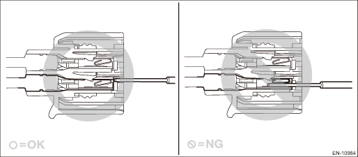
5. When measuring the voltage or resistance of individual sensor or all electrical control modules, use a tapered pin with a diameter of 0.6 mm (0.024 in) or less and touch it to the tip of terminal.
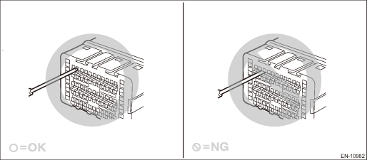
Never insert the tapered pin into the terminal because it deforms inside which may lead to a malfunction.
CAUTION:
When replacing the ECM, be careful not to use the ECM of wrong specification to avoid any damage on the fuel injection system.
NOTE:
When replacing the ECM of the models with immobilizer, immobilizer system must be registered. For detailed operation procedure, refer to the “REGISTRATION MANUAL FOR IMMOBILIZER”.
6. Take care not to allow water to get into the connectors when servicing or washing the vehicle in rainy weather. Avoid exposure to water even if the connectors are waterproof.
7. Use ECM mounting stud bolts for the grounding point when measuring voltage and resistance inside the passenger compartment.
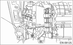
(A) | Stud bolt |
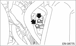
8. Use the engine ground terminal or engine assembly for the grounding point when measuring the voltage and resistance in engine compartment.
9. All parts related to the engine control system are precision parts. Do not drop or otherwise apply impact. Do not reuse the parts that are dropped accidentally.
10. Observe the following cautions when installing a radio in vehicle.
CAUTION:
• The antenna must be kept as far apart as possible from the ECM. Electrical Component Location > LOCATION">
• The antenna feeder must be placed as far apart as possible from the ECM and engine control system harness.
• Carefully adjust the antenna for correct matching.
• When mounting a large power type radio, pay special attention to the three items mentioned above.
• Incorrect installation of the radio may affect the operation of ECM.
11. When disconnecting the fuel hose, release the fuel pressure. Fuel > PROCEDURE">
12. Warning lights may illuminate when performing driving test with jacked-up or lifted-up condition, but this is not a system malfunction. The reason for this is the rotating speed difference between the front and rear wheels. When engine control system diagnosis is finished, perform the VDC memory clearance procedure of self-diagnosis function. Clear Memory Mode">

 Preparation tool
ENGINE (DIAGNOSTICS)(H4DO) > General DescriptionPREPARATION TOOL1. SPECIAL TOOLILLUSTRATIONTOOL NUMBERDESCRIPTIONREMARKS — SUBARU SELECT MONITOR 4Used for setting of each function and troubleshoo ...
Other materials:
Replacement
DIFFERENTIALS > Rear Differential Mount BushingREPLACEMENTCAUTION:• If there was so much rust in the rear differential mount bushing, remove the rust before starting work.• Apply the molybdenum grease on the square thread of the ST (shaft and nut) before use.1. Remove the rear differe ...
Component
INTAKE (INDUCTION)(H4DO) > General DescriptionCOMPONENT(1)Air intake duct(8)Air cleaner case (rear)Tightening torque: N·m (kgf-m, ft-lb)(2)Clip(9)ClipT1:1 (0.1, 0.7)(3)Cushion(10)Mass air flow and intake air temperature sensorT2:3 (0.3, 2.2)(4)Air cleaner case (front)(11)ClampT3:6 (0.6, 4. ...
Removal
SECURITY AND LOCKS > Access BuzzerREMOVAL1. Disconnect the ground cable from battery. NOTE">2. Lift up the vehicle.3. Remove the clips and screws, and turn over the front side of the mud guard - front RH.4. Remove the access buzzer.(1) Disconnect the connector.(2) Remove the clip and det ...
