Subaru Crosstrek Service Manual: Replacement
DIFFERENTIALS > Rear Differential Mount Bushing
REPLACEMENT
CAUTION:
• If there was so much rust in the rear differential mount bushing, remove the rust before starting work.
• Apply the molybdenum grease on the square thread of the ST (shaft and nut) before use.
1. Remove the rear differential. Rear Differential (T-type) > REMOVAL"> Rear Differential (VA-type) > REMOVAL">
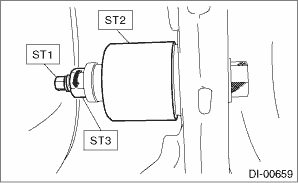
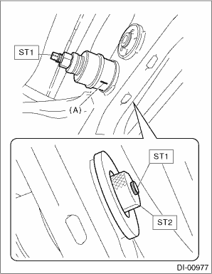
2. Fit the ST to the periphery of the sub frame cylinder, and make sure that the ST does not contact with welded spots or spatters.
| ST 41399FG010 | SPECIAL TOOL A |
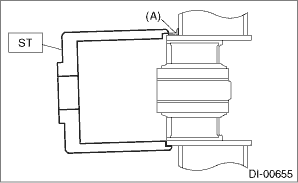
(A) | Welded spot |
3. If the ST contacts with welded spots or spatters, remove the excessive welds or spatters with sander or the equivalent so that the ST contacts the cylinder peripheral part.
CAUTION:
Performing the operation with the ST contacting with welded spots or spatters may break the ST. Be sure to remove excessive welds or spatters before the operation.
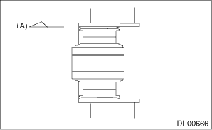
4. Set ST1, ST2, ST3, ST4 and ST5 as shown in the figure.
| ST1 41399FG091 | SPECIAL TOOL SHAFT |
| ST2 41399FG070 | SPECIAL TOOL NUT |
| ST3 41399FG050 | SPECIAL TOOL SLEEVE |
| ST4 41399FG080 | SPECIAL TOOL BEARING |
| ST5 41399FG010 | SPECIAL TOOL A |
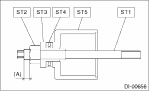
(A) | 5 mm (0.2 in) or less |
5. Fit and hold the ST1 and ST2 to the rear differential mount bushing from the rear side of vehicle.
| ST1 41399FG031 | SPECIAL TOOL C |
| ST2 41399FG061 | SPECIAL TOOL RING |
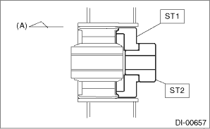
(A) | Front side of vehicle |
6. Insert the ST set in the step 4) through the rear differential mount bushing hole from the front side of vehicle, and screw in the ST1 by hand till the front end of ST1 comes out slightly from the rear end of ST2.
| ST1 41399FG091 | SPECIAL TOOL SHAFT |
| ST2 41399FG061 | SPECIAL TOOL RING |
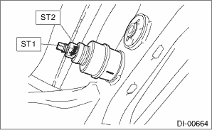
7. Hold the ST1 to prevent it from rotating, and screw in the ST3 by hand till there is no loose fit on the ST2.
CAUTION:
When setting the ST to the vehicle, always make sure that the ST2 fits the periphery of the sub frame cylinder and is not tilted.
| ST1 41399FG091 | SPECIAL TOOL SHAFT |
| ST2 41399FG010 | SPECIAL TOOL A |
| ST3 41399FG070 | SPECIAL TOOL NUT |
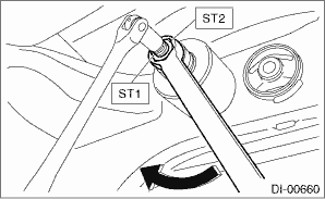
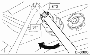
8. Hold the ST1 with a tool to prevent it from rotating, and screw in the ST2 to remove the rear differential mount bushing.
CAUTION:
• Rotation of ST1 will damage the screw at the rear end of rear differential mount bushing. Never rotate the ST1.
• If the ST starts to tilt while removing the rear differential mount bushing, stop the work and set the ST again.
| ST1 41399FG091 | SPECIAL TOOL SHAFT |
| ST2 41399FG070 | SPECIAL TOOL NUT |
9. Set ST1, ST2, ST3, ST4, ST5 and rear differential mount bushing as shown in the figure.
NOTE:
• Set the ST2 nut near to the end of ST1 screw.
• Hold the rear differential mount bushing with the arrow marked side facing toward the rear of the vehicle, and set the rear differential mount bushing to the ST so that the arrow mark faces upward.
• Mark the bottom end of rear differential mount bushing to identify the installing direction.
| ST1 41399FG091 | SPECIAL TOOL SHAFT |
| ST2 41399FG070 | SPECIAL TOOL NUT |
| ST3 41399FG050 | SPECIAL TOOL SLEEVE |
| ST4 41399FG080 | SPECIAL TOOL BEARING |
| ST5 41399FG020 | SPECIAL TOOL B |
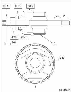
(A) | 8 mm (0.31 in) or more |
(B) | Arrow mark |
(C) | Marked position |
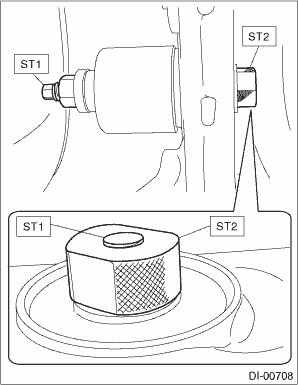
10. Attach ST1 to the ST2, and fit and hold the STs as a unit to the sub frame from the rear side of vehicle.
| ST1 41399FG061 | SPECIAL TOOL RING |
| ST2 41399FG041 | SPECIAL TOOL D |
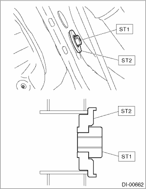
11. Insert the ST and rear differential mount bushing set in the step 9) through the sub frame from the front side of vehicle, and screw in the ST1 by hand till the front end of ST1 comes out slightly from the rear end of ST2.
CAUTION:
Set the rear differential mount bushing with its mark facing the bottom end direction.
| ST1 41399FG091 | SPECIAL TOOL SHAFT |
| ST2 41399FG061 | SPECIAL TOOL RING |
(A) | Mark |
12. Hold the ST1 to prevent it from rotating, and screw in the ST2 by hand till there is no loose fit on the ST and the rear differential mount bushing.
CAUTION:
Make sure that the ST and rear differential mount bushing are not tilted.
| ST1 41399FG091 | SPECIAL TOOL SHAFT |
| ST2 41399FG070 | SPECIAL TOOL NUT |
13. Screw in the ST2 while holding the ST1 with a tool to prevent it from rotating, and press-fit the rear differential mount bushing to the front end of sub frame cylinder.
| ST1 41399FG091 | SPECIAL TOOL SHAFT |
| ST2 41399FG070 | SPECIAL TOOL NUT |
14. Make sure that the rear differential mount bushing is inserted to the front end of sub frame cylinder.
(A) | Front side of vehicle |
15. Install the rear differential. Rear Differential (T-type) > INSTALLATION"> Rear Differential (VA-type) > INSTALLATION">
 Inspection
DIFFERENTIALS > Rear Differential Mount BushingINSPECTIONCheck the rear differential mount bushing for cracks, hardening or damage. If cracking, hardening or damage is excessive, replace rear diffe ...

Other materials:
Dtc p0303 cylinder 3 misfire detected
ENGINE (DIAGNOSTICS)(H4DO) > Diagnostic Procedure with Diagnostic Trouble Code (DTC)DTC P0303 CYLINDER 3 MISFIRE DETECTEDNOTE:For the diagnostic procedure, refer to DTC P0304. Diagnostic Procedure with Diagnostic Trouble Code (DTC) > DTC P0304 CYLINDER 4 MISFIRE DETECTED">1. OUTLINE O ...
Dtc b28a8 internal stereo camera communication 2
EyeSight (DIAGNOSTICS) > Diagnostic Procedure with Diagnostic Trouble Code (DTC)DTC B28A8 INTERNAL STEREO CAMERA COMMUNICATION 2Detected when error occurs in the communication data inside the control module caused by external factors such as noises.NOTE:If the same DTC is still detected after the ...
Note
GLASS/WINDOWS/MIRRORS > Remote Control Mirror SystemNOTEFor procedure of each component in the remote control mirror system, refer to the respective section.• Outer mirror assembly: Outer Mirror Assembly">• Remote control mirror switch: Remote Control Mirror Switch"> ...
