Subaru Crosstrek Service Manual: Adjustment
FRONT SUSPENSION > Wheel Alignment
ADJUSTMENT
CAUTION:
When the wheel alignment has been adjusted, perform the adjustment of the VDC. VDC Control Module and Hydraulic Control Unit (VDCCM&H/U) > ADJUSTMENT">
1. FRONT CAMBER
1. Adjust the camber angle to the following value.
Tire size | Camber (difference between RH and LH 45' or less) | |
P225/55R17 225/55R17 | 0°10'±0°30' | |
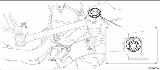
2. Loosen the two flange nuts located at the front lower section of the strut.
NOTE:
When the adjusting bolt needs to be loosened or tightened, hold its head with a wrench and turn the flange nut.
3. Turn the camber adjusting bolt so that the camber is set at specification.
NOTE:
Moving the adjusting bolt by one scale changes the camber by approximately 0°15'.
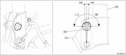
(a) | Strut ASSY | (d) | Outer direction | (g) | Camber is decreased. |
(b) | Adjusting bolt | (e) | Inner direction | ||
(c) | Housing ASSY - front axle | (f) | Camber is increased. |
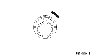
To increase camber. | |
Rotate the left side counterclockwise. | Rotate the right side clockwise. |
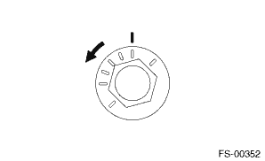
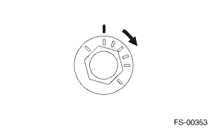
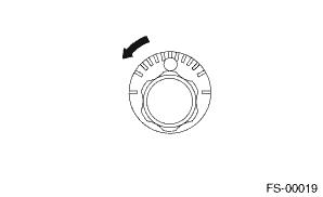
To decrease camber. | |
Rotate the left side clockwise. | Rotate the right side counterclockwise. |
4. Tighten two new flange nuts.
Tightening torque:
155 N·m (15.81 kgf-m, 114.3 ft-lb)
2. ADJUSTMENT OF DIFFERENCE BETWEEN RIGHT AND LEFT STEERING ANGLES
1. Operate the steering system from lock to lock and stop operating it at the center position from lock to lock, and then install the steering wheel in the straight-ahead position.
NOTE:
Using of the steering wheel angle sensor output values shown on Subaru Select Monitor will facilitate your work.
2. Before adjusting toe-in, be sure to adjust the steering wheel in the straight-ahead position (steering angle sensor output: 0 deg).
3. FRONT WHEEL TOE-IN
When adjusting the toe-in, adjust it to the following value. Wheel Alignment > ADJUSTMENT">
Toe-in: Adjustment value
0±2 mm (0±0.08 in)
1. Check that the left and right wheel steering angles are within specification.
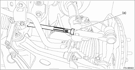
2. Loosen the left and right side steering tie-rod lock nuts (a).
3. Turn the left and right tie-rods by equal amounts until the toe-in is at the specification.
NOTE:
Both the left and right tie-rods are right-hand threaded. To increase toe-in, turn both tie-rods clockwise by equal amount (viewing from the inside of vehicle).
4. Tighten the tie-rod lock nut (a).
Tightening torque:
85 N·m (8.67 kgf-m, 62.7 ft-lb)
5. Check and correct the tie-rod boot if twisted.
4. REAR WHEEL TOE-IN
When adjusting, adjust it to the following value.
Toe-in: Adjustment value
0±2 mm (0±0.08 in)
1. Loosen the self-locking nut for the lateral link assembly - front.
NOTE:
When loosening or tightening the adjusting bolt, hold the bolt head and turn the self-locking nut.
2. Turn the adjusting bolt until toe-in is within the specification.
NOTE:
When the left and right wheels are adjusted for toe-in at the same time, the movement of one scale graduation changes toe-in by approx. 1.3 mm (0.05 in).
To increase toe-in. | |
Rotate the left side clockwise. | Rotate the right side counterclockwise. |
To decrease toe-in. | |
Rotate the left side counterclockwise. | Rotate the right side clockwise. |
3. Attach and tighten a new self-locking nut.
Tightening torque:
100 N·m (10.20 kgf-m, 73.8 ft-lb)
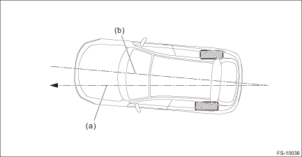
5. THRUST ANGLE
When adjusting, adjust it to the following value.
Thrust angle: Adjustment value
0°±20'
Less than 20' when “L” is 15 mm (0.6 in) or less
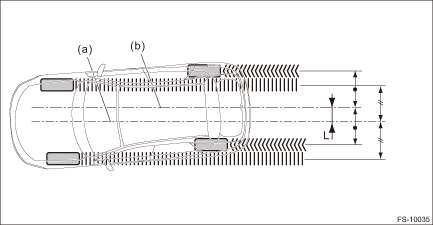
(a) | Center line of loci (front axle) | (b) | Center line of loci (rear axle) |
1. Make thrust angle adjustments by turning the toe-in adjusting bolts of the rear suspension equally in the same direction.
2. When one rear wheel is adjusted in a toe-in direction, adjust the other rear wheel equally in toe-out direction, in order to make the thrust angle adjustment.
3. When the left and right adjusting bolts are turned by one graduation, the thrust angle will change approx. 15'. (“L” is approx. 11 mm (0.43 in).)
NOTE:
Thrust angle is a mean value of left and right wheel toe angles in relation to the vehicle body center line.
Vehicle is driven straight in the thrust angle direction while slanting in the oblique direction depending on the degree of the mean thrust angle.
(a) | Thrust angle | (b) | Body center line |
Thrust angle:
γ = (α − β)/2
α: Rear RH wheel toe-in angle
β: Rear LH wheel toe-in angle
Substitute only the positive toe-in values from each wheel into α and β in the calculation.
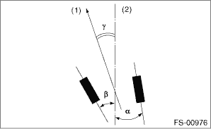
(1) | Front |
(2) | Body center line |
 Wheel alignment
...
 Inspection
FRONT SUSPENSION > Wheel AlignmentINSPECTIONCheck the following items before performing the wheel alignment measurement.• Tire inflation pressure• Uneven wear of RH and LH tires, or dif ...
Other materials:
Disassembly
MANUAL TRANSMISSION AND DIFFERENTIAL(5MT) > Front Differential AssemblyDISASSEMBLY1. DIFFERENTIAL CASE ASSEMBLY1. Remove the twelve bolts and remove hypoid driven gear.(A)Hypoid driven gear2. Drive out the straight pin from differential assembly toward hypoid driven gear side.ST 899904100STRAI ...
Engine oil setting
1. Perform the preparation steps according
to "Preparation for maintenance settings"
2. Operate the "
" or "
" switch to
select the "Engine Oil" item. Then push
the
button.
3. Select the setting location (month, day,
year or distance) by operating the "
" or ...
Dtc p2109 throttle/pedal position sensor "a" minimum stop performance
ENGINE (DIAGNOSTICS)(H4DO) > Diagnostic Procedure with Diagnostic Trouble Code (DTC)DTC P2109 THROTTLE/PEDAL POSITION SENSOR "A" MINIMUM STOP PERFORMANCENOTE:For the diagnostic procedure, refer to DTC P2101. Diagnostic Procedure with Diagnostic Trouble Code (DTC) > DTC P2101 THROTTL ...
