Subaru Crosstrek Service Manual: Wiring diagram
CONTROL SYSTEMS > AT Shift Lock Control System
WIRING DIAGRAM
1. MODEL WITHOUT PUSH BUTTON IGNITION SWITCH
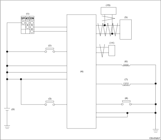
(1) | Ignition switch | (5) | TCM (shift range information) | (9) | Battery |
(2) | Stop light and brake switch | (6) | Key lock solenoid | (10) | ECM (delivery (test) mode signal) |
(3) | Key warning switch | (7) | Shift lock solenoid | (11) | VDC CM (vehicle speed information) |
(4) | Body integrated unit | (8) | “P” range switch |
2. MODEL WITH PUSH BUTTON IGNITION SWITCH
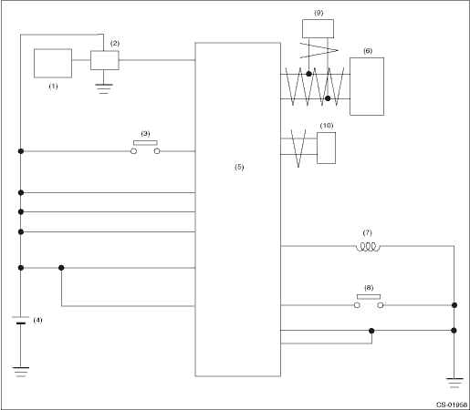
(1) | Keyless access CM | (5) | Body integrated unit | (8) | “P” range switch |
(2) | IG relay 1 (push button start) | (6) | TCM (shift range information) | (9) | ECM (delivery (test) mode signal) |
(3) | Stop light and brake switch | (7) | Shift lock solenoid | (10) | VDC CM (vehicle speed information) |
(4) | Battery |
 Location
CONTROL SYSTEMS > AT Shift Lock Control SystemLOCATION1. MODEL WITHOUT PUSH BUTTON IGNITION SWITCH(1)TCM (“P” range)(4)Key cylinder (with built-in key warning switch)(6)“P” ...

Other materials:
Note
LIGHTING SYSTEM > Headlight SystemNOTEFor operation procedures of each component of the headlight system, refer to the respective section.• Headlight Assembly: Headlight Assembly">• Headlight bulb: Headlight Bulb">• Combination switch (light): Combination Swit ...
Dtc p0507 idle control system rpm - higher than expected
ENGINE (DIAGNOSTICS)(H4DO) > Diagnostic Procedure with Diagnostic Trouble Code (DTC)DTC P0507 IDLE CONTROL SYSTEM RPM - HIGHER THAN EXPECTEDDTC DETECTING CONDITION:Detected when two consecutive driving cycles with fault occur.TROUBLE SYMPTOM:Engine keeps running at higher speed than specified idl ...
Dtc b28a6 internal stereo camera communication 1
EyeSight (DIAGNOSTICS) > Diagnostic Procedure with Diagnostic Trouble Code (DTC)DTC B28A6 INTERNAL STEREO CAMERA COMMUNICATION 1Detected when communication error occurs inside the stereo camera.DTC DETECTING CONDITION:Communication error occurs inside the stereo camera.TROUBLE SYMPTOM:All functio ...
