
Subaru Crosstrek Service Manual: System block diagram
Blind Spot Detection/Rear Cross Traffic Alert (DIAGNOSTICS) > Control Module I/O Signal
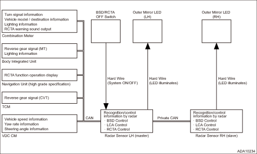
SYSTEM BLOCK DIAGRAM
• Blind Spot Detection/Rear Cross Traffic Alert system consists of the following.
• There is a control ECM in the radar sensor main body, which performs the vehicle identification and the alert judgment control.
• The LH/RH radar sensors are identified as Master/Slave for control purposes. They are connected by the private CAN to execute the controls through mutual communication. The radar on the Master side receives the input from the vehicle CAN and the SRVD OFF switch, and information necessary for control can be obtained from other modules via the vehicle CAN.
• The outer mirror LED is directly driven by the signal from the radar sensor.
 Electrical specification
Blind Spot Detection/Rear Cross Traffic Alert (DIAGNOSTICS) > Control Module I/O SignalELECTRICAL SPECIFICATION1. RADAR SENSORTerminal No.ContentMeasuring conditionStandardRadar sensor LH (master)R ...
 Wiring diagram
Blind Spot Detection/Rear Cross Traffic Alert (DIAGNOSTICS) > Control Module I/O SignalWIRING DIAGRAMRefer to “BSD/RCTA System” in the wiring diagram. Blind Spot Detection/Rear Cross T ...
Other materials:
Removal
HVAC SYSTEM (HEATER, VENTILATOR AND A/C) > EvaporatorREMOVALCAUTION:Before handling the airbag system components, refer to “CAUTION” of “General Description” in “AIRBAG SYSTEM”. General Description > CAUTION">1. Disconnect the ground cable from batt ...
BSD/RCTA warning indicator
System malfunction
BSD/RCTA malfunction message
At first, this message will appear
Then this message will appear
BSD/RCTA warning indicator
If a malfunction occurs within the BSD/RCTA system of the Subaru Ascent, a sequence
of warning messages will be displayed followed by the act ...
Inspection
LIGHTING SYSTEM > Day Time Running ResistorINSPECTION1. Measure the resistance between connector terminals.Preparation tool:Circuit testerTerminal No.Inspection conditionsSpecificationConnection diagram1 — 2Always1.13±0.05 ?2. Replace the resistor assembly - daytime running light if the inspec ...
