Subaru Crosstrek Service Manual: Removal
MECHANICAL(H4DO) > Cam Carrier
REMOVAL
1. CAM CARRIER RH
1. Remove the engine from the vehicle. Engine Assembly > REMOVAL">
2. Remove the chain cover. Chain Cover > REMOVAL">
3. Remove the timing chain RH. Timing Chain Assembly > REMOVAL">
4. Remove the cam sprocket RH. Cam Sprocket > REMOVAL">
NOTE:
This operation is required only when disassembling the cam carrier RH.
5. Remove the rocker cover RH. Rocker Cover > REMOVAL">
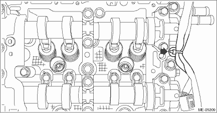
6. Remove the clip holding the engine harness from cam carrier RH.
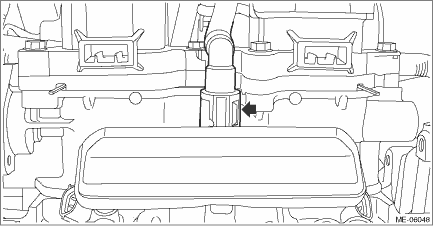
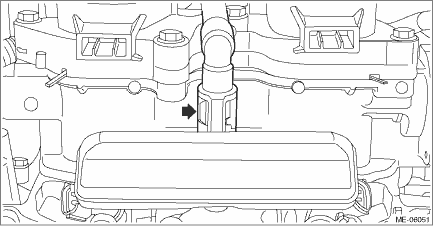
7. Remove the water pipe assembly RH. Water Pipe Assembly > REMOVAL">
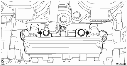
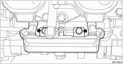
8. Remove the fuel pipe RH and the fuel injector RH.
(1) Disconnect the connector from fuel injector RH.
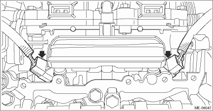
(2) Disconnect the quick connector from fuel pipe RH.
NOTE:
Disconnect the quick connector as shown in the figure.
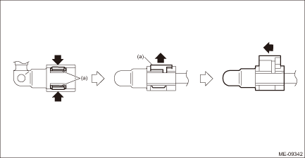
(a) | Slider |
(3) Remove the bolts securing the fuel pipe RH, and remove the fuel pipe RH and the fuel injector RH.
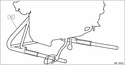
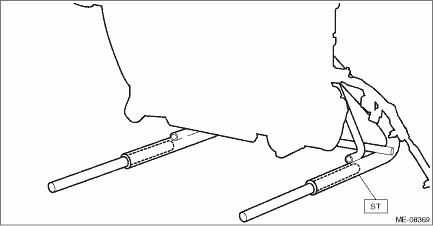
9. Insert the steel rods into ST, and set the engine so that the camshaft RH is facing up.
CAUTION:
• If the engine is standing on one side without inserting the steel rod into ST, engine may lose balance and fall down. Be sure to insert the steel rod into ST to extend the length.
• Use the steel rod with enough strength.
• Be careful not to pinch the engine harness with ST.
| ST 499817100 | ENGINE STAND |
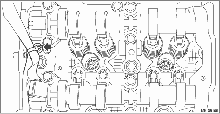
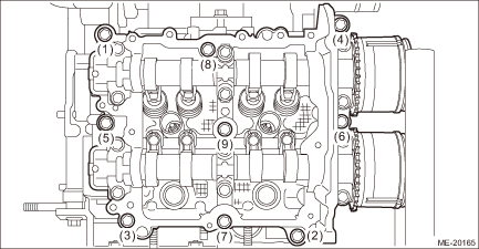
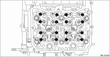
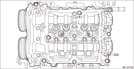
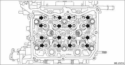
10. Loosen the bolts holding the cam carrier RH equally, a little at a time in numerical sequence as shown in the figure and remove the cam carrier RH.
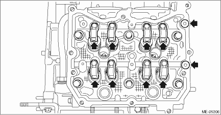
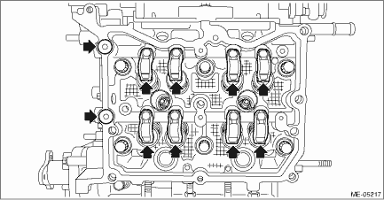
11. Remove the O-ring and the roller rocker arm from cylinder head RH.
NOTE:
Be careful not to confuse the roller rocker arms.
12. Remove the valve shim and the roller rocker arm pivot from cylinder head RH.
NOTE:
Be careful not to confuse the valve shim and the roller rocker arm pivot.
13. Remove the liquid gasket from cam carrier RH and cylinder head RH.
2. CAM CARRIER LH
1. Remove the engine from the vehicle. Engine Assembly > REMOVAL">
2. Remove the chain cover. Chain Cover > REMOVAL">
3. Remove the timing chain LH. Timing Chain Assembly > REMOVAL">
4. Remove the cam sprocket LH. Cam Sprocket > REMOVAL">
NOTE:
This operation is required only when disassembling the cam carrier LH.
5. Remove the rocker cover LH. Rocker Cover > REMOVAL">
6. Remove the clip holding the engine harness from cam carrier LH.
7. Remove the water pipe assembly LH. Water Pipe Assembly > REMOVAL">
8. Remove the fuel pipe LH and the fuel injector LH.
(1) Disconnect the connector from fuel injector LH.
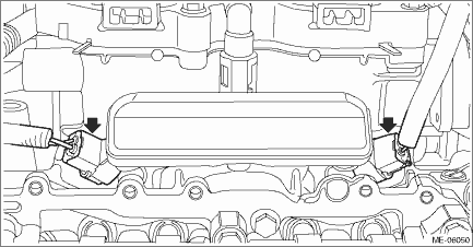
(2) Disconnect the quick connector from fuel pipe LH.
NOTE:
Disconnect the quick connector as shown in the figure.
(a) | Slider |
(3) Remove the bolts securing the fuel pipe LH, and remove the fuel pipe LH and the fuel injector LH.
9. Insert the steel rods into ST, and set the engine so that the camshaft LH is facing up.
CAUTION:
• If the engine is standing on one side without inserting the steel rod into ST, engine may lose balance and fall down. Be sure to insert the steel rod into ST to extend the length.
• Use the steel rod with enough strength.
• Be careful not to pinch the engine harness with ST.
| ST 499817100 | ENGINE STAND |
10. Loosen the bolts holding the cam carrier LH equally, a little at a time in numerical sequence as shown in the figure and remove the cam carrier LH.
11. Remove the O-ring and the roller rocker arm from cylinder head LH.
NOTE:
Be careful not to confuse the roller rocker arms.
12. Remove the valve shim and the roller rocker arm pivot from cylinder head LH.
NOTE:
Be careful not to confuse the valve shim and the roller rocker arm pivot.
13. Remove the liquid gasket from cam carrier LH and cylinder head LH.
 Assembly
MECHANICAL(H4DO) > Cam CarrierASSEMBLY1. CAM CARRIER RH1. Install the filter to the cam carrier RH.NOTE:Use a new filter.Filter insert position:Cam carrier RH end face 0+0 −0.5 mm (+0 − ...
 Disassembly
MECHANICAL(H4DO) > Cam CarrierDISASSEMBLY1. CAM CARRIER RH1. Loosen the bolts (front camshaft cap RH, intake center camshaft cap RH, intake rear camshaft cap RH, exhaust center camshaft cap RH, and ...
Other materials:
Note
LIGHTING SYSTEM > Auto Headlight Beam Leveler SystemNOTEFor operation procedures of each component of the auto headlight beam leveler system, refer to the respective section.• Auto headlight beam leveler CM: Auto Headlight Beam Leveler Control Module">• Vehicle height sensor: ...
Interior light off delay timer setting
1. Perform the preparation steps according
to "Preparation for car settings"
2. Operate the " " or "
" switch to
select the "Interior Light" item. Then push
the button.
3. The current setting will be displayed.
Push the button to enter the
selection
mode.
4. Select ...
Preparation for overhaul Procedure
MANUAL TRANSMISSION AND DIFFERENTIAL(5MT) > Preparation for OverhaulPROCEDURE1. Clean oil, grease, dirt and dust from the transmission.2. When transmission gear oil remains in the transmission, using the TORX® bit T70, remove the drain plug, and drain the gear oil completely.3. Attach the drain ...
