Subaru Crosstrek Service Manual: Removal
FUEL INJECTION (FUEL SYSTEMS)(H4DO) > Fuel Tank
REMOVAL
WARNING:
Place “NO OPEN FLAMES” signs near the working area.
CAUTION:
• Be careful not to spill fuel.
• Catch the fuel from the tubes using a container or cloth.
1. Release the fuel pressure. Fuel > PROCEDURE">
2. Drain fuel. Fuel > PROCEDURE">
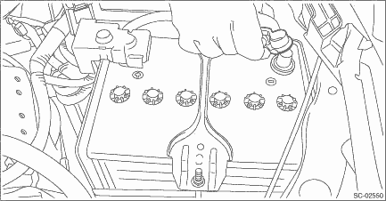
3. Disconnect the ground cable from battery.
4. Remove the rear seat cushion. Rear Seat > REMOVAL">
5. Remove the service hole cover of fuel pump.
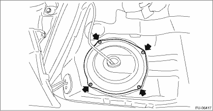
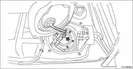
6. Disconnect connectors from the fuel pump, and move aside the service hole cover.

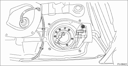
7. Remove the service hole cover of fuel sub level sensor.

8. Disconnect connectors from the fuel sub level sensor, and move aside the service hole cover.
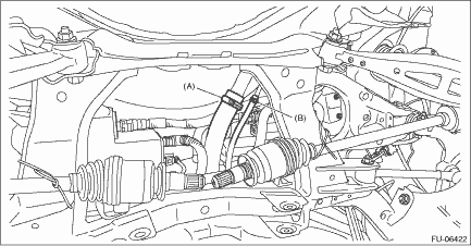
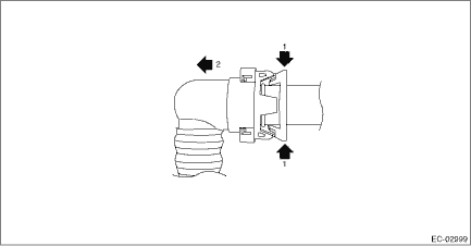
9. Disconnect the quick connector on the fuel delivery tube.
NOTE:
Disconnect the quick connector as shown in the figure.

(a) | Slider |
10. Lift up the vehicle.
11. Remove the rear exhaust pipe and muffler. Rear Exhaust Pipe > REMOVAL"> Muffler > REMOVAL">
12. Remove the rear differential. Rear Differential (T-type) > REMOVAL"> Rear Differential (VA-type) > REMOVAL">
13. Disconnect the fuel filler hose (A) and evaporation hose (B) from the fuel filler pipe assembly.
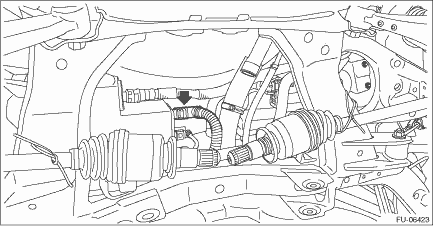
14. Disconnect the vent tube from canister.
NOTE:
Disconnect the quick connector as shown in the figure.
15. Remove the fuel tank protector. Fuel Tank Protector > REMOVAL">
16. Remove the heat shield cover and stopper.
17. Remove the stay - rear frame COMPL.
18. Support the fuel tank with a transmission jack, remove the bolts from the fuel tank band, and remove the fuel tank from the vehicle.
WARNING:
• A helper is required to perform this work.
• Fuel may remain in the fuel tank. This will cause the left and right sides to be unbalanced. Be careful not to drop the fuel tank.
 Inspection
FUEL INJECTION (FUEL SYSTEMS)(H4DO) > Fuel TankINSPECTION1. Check that the fuel tank and fuel pipe have no deformation, cracks and other damages.2. Check that the fuel hose and tube have no cracks, ...
 Installation
FUEL INJECTION (FUEL SYSTEMS)(H4DO) > Fuel TankINSTALLATION1. Support the fuel tank with a transmission jack, set the fuel tank in place, and temporarily tighten the bolts of the fuel tank band.WAR ...
Other materials:
Vehicle Dynamics Control system
WARNING
Even when driving a Subaru Ascent equipped with the Vehicle Dynamics Control
system, always remain attentive and cautious. Relying too heavily on electronic
assistance systems can lead to dangerous situations and potentially serious accidents.
CAUTION
Although the Subaru Ascent is ...
Conditions in which front passenger's SRS frontal airbag is activated
The Subaru Ascent is equipped with an intelligent SRS frontal airbag system that
activates based on real-time analysis of the front passenger seat conditions. The
front passenger's SRS frontal airbag is designed to deploy during an impact when
specific criteria are met, ensuring optimal sa ...
Preparation for car settings
1. Turn the ignition switch to the "ON"
position.
2. Push and hold the button to
show
the selection screen.
3. After the selection screen is displayed,
operate the " " or "
" switch to show the
"Car Setting" item. Then, push the
button. ...
