Subaru Crosstrek Service Manual: Removal
FRONT SUSPENSION > Front Crossmember
REMOVAL
CAUTION:
• The power steering control module continues to operate after the engine stops and calculate the temperature in the control module. Therefore, before starting service of the power steering system which requires disconnection of the connector, stop the engine and allow approx. 30 minutes until the control module becomes cold.
• Before removal or installation, be sure to remove any foreign matter (dust, moisture, oil, etc.) from the power steering control module connector.
1. Disconnect the ground cable from battery. NOTE">
2. Adjust the tilt position of the steering column to the lowest position and lock the tilt lever.
3. Lift up the vehicle, and then remove the front wheels.
4. Remove the under cover - front. Front Under Cover > REMOVAL">
5. Remove the universal joint assembly - steering. Universal Joint > REMOVAL">
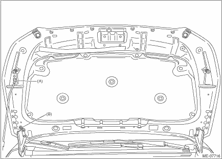
6. Change the front hood stay position from (A) to (B), and completely open the front hood.
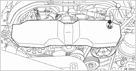
7. Remove the V-belt covers.
8. Disconnect the connector and harness clamp from power steering control module.
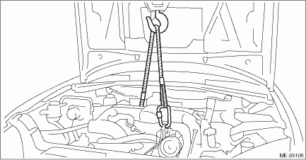
9. Support the engine with a lifting device and wire ropes.
(1) Support the engine with a lifting device and wire ropes.
(2) While lifting up the vehicle, also raise up the lifting device.
CAUTION:
When lifting up the vehicle, raise up wire ropes at the same time.
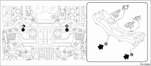
10. Remove the nuts which secure the engine mounting.
(1) Raise up the lifting device, and lift the engine by approx. 10 mm (0.39 in).
(2) Remove the nuts which secure the engine mounting to the front crossmember assembly.
11. Remove the front exhaust pipe. Front Exhaust Pipe > REMOVAL">
12. Remove the front crossmember support. Front Crossmember Support Plate > REMOVAL">
13. Remove the front stabilizer. Front Stabilizer > REMOVAL">
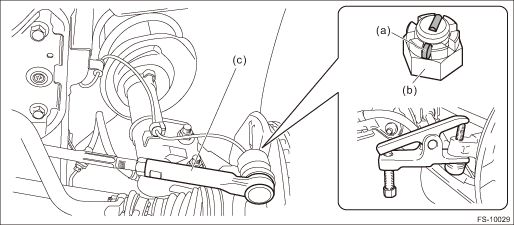
14. Disconnect the tie-rod end.
(1) Pull out the cotter pin (a).
(2) Remove the castle nut (b).
(3) Using a tie-rod end puller, remove the tie-rod end (c).
Preparation tool:
Tie-rod end puller
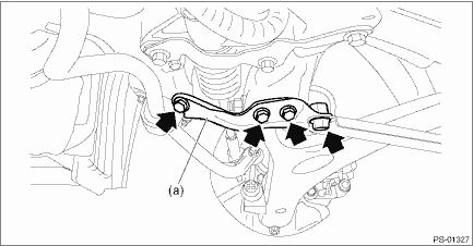
15. Remove the support plate - front crossmember (a).
16. Remove the front arm assembly. Front Arm > REMOVAL">
17. Support the front crossmember assembly using a jack, and remove the bolts which hold the crossmember on the body.
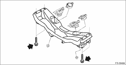
18. Slowly lower the front crossmember assembly with the steering gearbox assembly as a single unit.
CAUTION:
When removing the crossmember, make sure that the tie-rod end does not interfere with the drive shaft boot.
19. Remove the steering gearbox assembly from the front crossmember assembly.
 Installation
FRONT SUSPENSION > Front CrossmemberINSTALLATION1. Check the crossmember for damage or cracks, and correct or replace if defective.2. Install the universal joint assembly - steering. Universal Joi ...

Other materials:
Caution
IMMOBILIZER (DIAGNOSTICS) > General DescriptionCAUTIONCAUTION:• Do not use the electrical test equipment on the airbag system wiring harnesses and connector circuits.• Be careful not to damage the airbag system wiring harness.• While diagnostic items are being checked, do not op ...
List
AIRBAG SYSTEM (DIAGNOSTICS) > Read Current DataLISTItemDisplayNoteTrip Count — — Count — — Time Count [msec] — — Belt Buckle Switch RHUnbelted/Belted“Belted” when passenger’s seat belt is fastened“Unbelted” when passenger’s seat belt is not faste ...
Dtc p0391 camshaft position sensor "b" circuit range/performance bank 2
ENGINE (DIAGNOSTICS)(H4DO) > Diagnostic Procedure with Diagnostic Trouble Code (DTC)DTC P0391 CAMSHAFT POSITION SENSOR "B" CIRCUIT RANGE/PERFORMANCE BANK 2NOTE:For the diagnostic procedure, refer to DTC P0390. Diagnostic Procedure with Diagnostic Trouble Code (DTC) > DTC P0390 CAMSH ...
