Subaru Crosstrek Service Manual: Removal
DRIVE SHAFT SYSTEM > Front Axle
REMOVAL
1. Lift up the vehicle, and then remove the front wheels.
2. Remove the axle nut.
CAUTION:
Do not loosen the axle nut while the front axle is loaded. Doing so may damage the hub unit bearing.
(1) Lift the crimped section of axle nut.
(2) Remove the axle nut using a socket wrench while depressing the brake pedal.

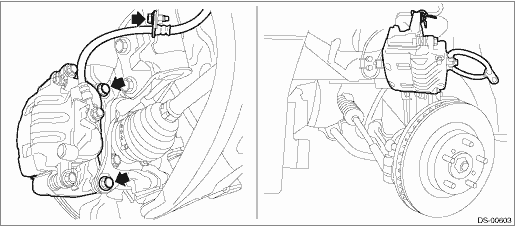
3. Remove the caliper body assembly from the front axle housing.
(1) Remove the mounting bolts and the brake hose bracket, and remove the caliper body assembly.
(2) Prepare wiring harnesses etc. to be discarded, and suspend the caliper body assembly from the strut assembly.
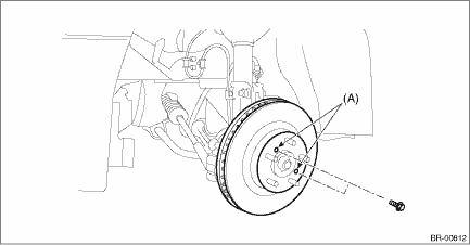
4. Remove the disc rotor.
NOTE:
When the disc rotor is difficult to be removed from the front hub unit bearing, screw in 8 mm (0.31 in) bolt to the threaded part of the disc rotor (A), and remove the disc rotor.
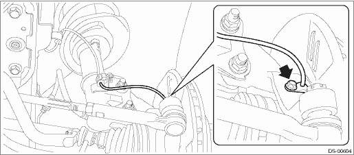
5. Remove the bolts, and remove the front ABS wheel speed sensor.
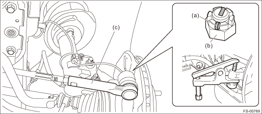
6. Disconnect the tie-rod end.
(1) Pull out the cotter pin (a).
(2) Remove the castle nut (b).
(3) Using a tie-rod ball joint puller, remove the tie-rod end (c).
CAUTION:
Be careful not to damage the boot of the joint.
Preparation tool:
Tie-rod ball joint puller
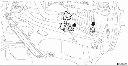
7. Remove the stabilizer link and ball joint.
CAUTION:
Be careful not to damage the boot of the joint.
8. Using a bar, remove the front drive shaft from transmission.
CAUTION:
Be careful not to allow the bar to damage holder area.
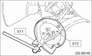
9. Remove the front drive shaft assembly from the front hub unit bearing.
NOTE:
If it is hard to remove, use the ST.
Preparation tool:
ST1: AXLE SHAFT PULLER (926470000)
ST2: AXLE SHAFT PULLER PLATE (28099PA110)
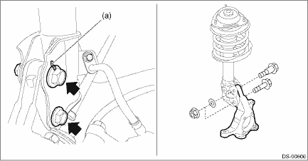
10. Remove the front axle housing.
(1) Place an alignment mark (a) on the adjusting bolt and the strut.
(2) Remove the adjusting bolts and flange bolts for the strut assembly, and then remove the front axle housing.
CAUTION:
• While holding the head of the adjusting bolt, loosen the flange nut.
• Be careful of the weight of front axle housing.
• Be careful not to damage the spline portion of the drive shaft.
11. Refer to “Front Hub Unit Bearing” for removal of the front hub unit bearing. Front Hub Unit Bearing > REMOVAL">
 Installation
DRIVE SHAFT SYSTEM > Front AxleINSTALLATION1. Install the front drive shaft assembly.CAUTION:• Do not hammer the drive shaft assembly when installing.• Use new axle nuts.(1) Insert the ...

Other materials:
Check cruise indicator light and cruise set indicator light
CRUISE CONTROL SYSTEM (DIAGNOSTICS) > Diagnostics with PhenomenonCHECK CRUISE INDICATOR LIGHT AND CRUISE SET INDICATOR LIGHTTROUBLE SYMPTOM:Cruise control can be set, but the CRUISE indicator and SET indicator do not illuminate.STEPCHECKYESNO1.CHECK CRUISE INDICATOR LIGHT AND CRUISE SET INDICATOR ...
Dtc b2275 engine start request control circuit
KEYLESS ACCESS WITH PUSH BUTTON START SYSTEM (DIAGNOSTICS) > Diagnostic Procedure with Diagnostic Trouble Code (DTC)DTC B2275 ENGINE START REQUEST CONTROL CIRCUITDTC detecting condition:• When malfunction is detected in engine start permission signal output circuit in the keyless access CM. ...
Inspection
FUEL INJECTION (FUEL SYSTEMS)(H4DO) > Main RelayINSPECTION1. Check that the main relay has no deformation, cracks or other damages.2. Measure the resistance between main relay terminals.Terminal No.Standard1 and 21 M? or more3 and 4130.4 — 230.8 ? (when 20°C (68°F))3. Conn ...
