Subaru Crosstrek Service Manual: Removal
CONTROL SYSTEMS > AT Shift Lock Solenoid and “P” Range Switch
REMOVAL
1. SOLENOID UNIT
1. Remove the AT select lever. Select Lever > REMOVAL">
2. Remove the spacer and gasket. Select Lever > DISASSEMBLY">
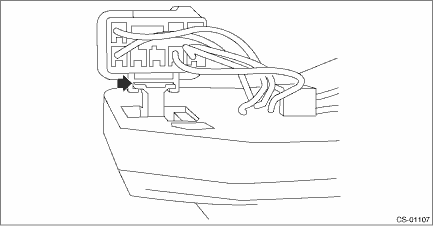
3. Using a flat tip screwdriver with a thin tip, remove the harness connector from the plate COMPL.
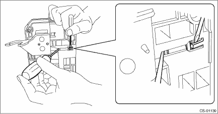
4. Raise the claw using a flat tip screwdriver with a thin tip, and remove the solenoid unit from the plate COMPL.
5. Remove the terminal of the solenoid unit using a flat tip precision screwdriver with a tip width of 1.3 mm (0.05 in) or less, KTC connector terminal tool ECC-1T or equivalent.
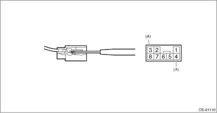
(A) | Solenoid unit terminals |
2. “P” RANGE SWITCH
For the removal of “P” range switch, refer to the procedure for AT select lever. Select Lever > DISASSEMBLY">
 Inspection
CONTROL SYSTEMS > AT Shift Lock Solenoid and “P” Range SwitchINSPECTIONSTEPCHECKYESNO1.CHECK SOLENOID UNIT.Measure the resistance of solenoid unit connector terminals.TerminalsNo. 4 — ...
 Installation
CONTROL SYSTEMS > AT Shift Lock Solenoid and “P” Range SwitchINSTALLATIONInstall in the reverse order of removal.NOTE:Insert the solenoid unit terminals to the harness connector.(A)Sole ...
Other materials:
Automatic front climate control operation
Front climate control screen
Air inlet selection
Air conditioner
Airflow mode
Fan speed
In the Subaru Ascent, selecting the automatic climate control mode allows the
system to intelligently regulate the cabin environment without constant manual adjustments.
Once activated, the s ...
Removal
MANUAL TRANSMISSION AND DIFFERENTIAL(5MT) > Manual Transmission AssemblyREMOVAL1. Disconnect the ground cable from battery.2. Remove the clip (A) from the air intake boot.3. Loosen the clamp (B) connecting the air intake boot and air cleaner case (rear).4. Loosen the clamp (C) which connects the ...
Inspection
PARKING BRAKE > Parking Brake Assembly (Rear Disc Brake)INSPECTION1. Measure the inner diameter of the rear disc rotor. If scoring or worn is found on the disc, replace the rear disc rotor.Disc rotor inner diameter:Specification: 170 mm (6.69 in)Service limit: 171 mm (6.73 in)2. Measure the linin ...
