
Subaru Crosstrek Service Manual: Removal
CONTINUOUSLY VARIABLE TRANSMISSION(TR580) > Primary Pulley and Secondary Pulley
REMOVAL
NOTE:
Always replace primary pulley and secondary pulley as an assembly because they are non-disassembled parts.
1. Remove the transmission assembly from the vehicle. Automatic Transmission Assembly > REMOVAL">
2. Remove the air breather hose. Air Breather Hose > REMOVAL">
3. Remove the control valve body. Control Valve Body > REMOVAL">
4. Remove the transmission harness. Transmission Harness > REMOVAL">
5. Remove the turbine speed sensor. Turbine Speed Sensor > REMOVAL">
6. Remove the secondary speed sensor. Secondary Speed Sensor > REMOVAL">
7. Remove the primary speed sensor. Primary Speed Sensor > REMOVAL">
8. Remove the inhibitor switch. Inhibitor Switch > REMOVAL">
9. Remove the extension case. Extension Case > REMOVAL">
10. Remove the transfer clutch assembly. Transfer Clutch > REMOVAL">
11. Remove the transfer driven gear assembly. Transfer Driven Gear > REMOVAL">
12. Remove the parking pawl. Parking Pawl > REMOVAL">
13. Remove the reduction driven gear assembly. Reduction Driven Gear > REMOVAL">
14. Remove the oil pan and oil strainer. Oil Pan and Strainer > REMOVAL">
15. Remove the transmission control device. Transmission Control Device > REMOVAL">
16. Remove the transmission case. Transmission Case > REMOVAL">
17. Remove the reduction drive gear. Reduction Drive Gear > REMOVAL">
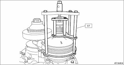
18. Set the ST to secondary pulley, expand the V groove of pulley, and then completely loosen the variator chain.
| ST 18769AA010 | EXPANDER PULLEY |
19. Remove the chain guide.
(1) Remove the chain guide from lubrication pipe.
(2) Detach the four claws to remove the chain guide.
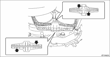
(3) Remove the lubrication pipe.
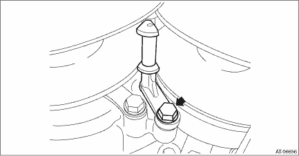
(4) Remove the support rod mounting bolts.
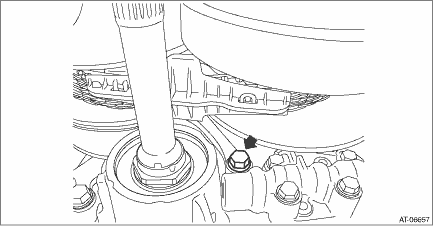
(5) Raise the support rod to remove the chain guide.
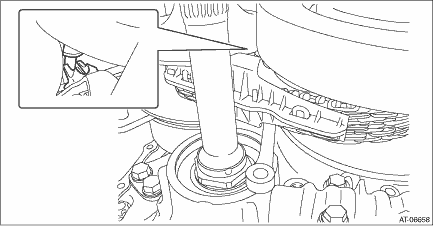
(6) Move the chain guide to the secondary pulley side.
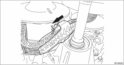
(7) Detach the four claws to remove the chain guide.
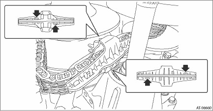
(8) Remove the support rod.
CAUTION:
Protect the both pulleys and variator chain from scratching.
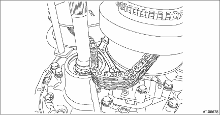
20. Remove the primary pulley mounting bolt.
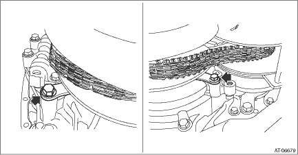
21. Remove the primary pulley from the reverse brake housing and intersect the V groove of secondary pulley and the V groove of primary pulley. Remove the variator chain from primary pulley, and remove the primary pulley.
CAUTION:
Cover the V grooves of secondary pulley and primary pulley with cloth to protect the both pulleys and variator chain from scratching.
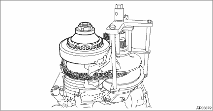
22. Remove the ST (EXPANDER PULLEY) from the secondary pulley.
23. Remove the variator chain from secondary pulley.
24. Remove the secondary pulley mounting bolts, and remove the secondary pulley.
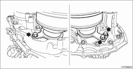
25. Remove the seal ring from drive pinion retainer.
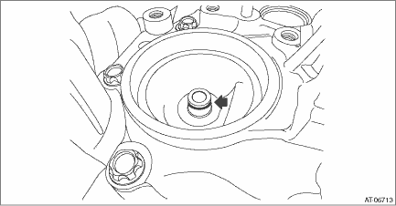
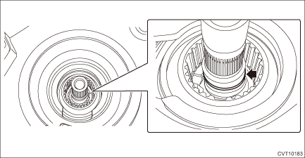
26. Remove the seal ring from the input shaft.
 Adjustment
CONTINUOUSLY VARIABLE TRANSMISSION(TR580) > Primary Pulley and Secondary PulleyADJUSTMENT1. PROCEDURE IN REPLACEMENT OF PRIMARY AND SECONDARY PULLEY, OR IN REPLACEMENT OF PRIMARY PULLEY, SECONDARY ...
 Inspection
CONTINUOUSLY VARIABLE TRANSMISSION(TR580) > Primary Pulley and Secondary PulleyINSPECTION• Check the surface of primary and secondary pulley cones for damage or wear.• Check the primary ...
Other materials:
Dtc p0746 pressure control solenoid "a" performance/stuck off
CONTINUOUSLY VARIABLE TRANSMISSION (DIAGNOSTICS) > Diagnostic Procedure with Diagnostic Trouble Code (DTC)DTC P0746 PRESSURE CONTROL SOLENOID "A" PERFORMANCE/STUCK OFFDTC detecting condition:Detected when two consecutive driving cycles with fault occur.Trouble symptom:• Shift cont ...
Preparation tool
WIPER AND WASHER SYSTEMS > General DescriptionPREPARATION TOOL1. SPECIAL TOOLILLUSTRATIONTOOL NUMBERDESCRIPTIONREMARKS — SUBARU SELECT MONITOR 4Used for setting of each function and troubleshooting for electrical system.NOTE:For detailed operation procedures of Subaru Select Monitor 4, refer to ...
Removal
COOLING(H4DO) > ThermostatREMOVAL1. ENGINE SIDE1. Disconnect the ground cable from battery. NOTE">2. Lift up the vehicle.3. Remove the under cover. Front Under Cover > REMOVAL">4. Drain engine coolant. Engine Coolant > REPLACEMENT">5. Remove the front exhaust pipe ...
