Subaru Crosstrek Service Manual: Removal
CLUTCH SYSTEM > Release Bearing and Lever
REMOVAL
1. Remove the transmission assembly from the vehicle.
Manual Transmission Assembly > REMOVAL">
2. Remove the two clips from the release lever and remove the release bearing.
CAUTION:
Be careful not to deform the clips.
3. Remove the dust cover.
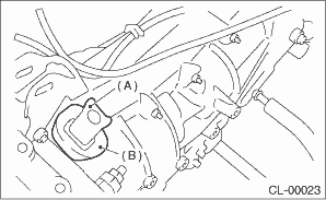
(A) | Release lever |
(B) | Dust cover |
4. Remove the attachment point of lever spring by inserting a screwdriver through the clutch housing release lever hole. Then remove the release lever.
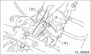
(A) | Release lever |
(B) | Screwdriver |
 Inspection
CLUTCH SYSTEM > Release Bearing and LeverINSPECTION1. RELEASE BEARINGCAUTION:Since this bearing is grease-sealed and is a non-lubrication type, do not wash with gasoline or any other solvent when s ...
 Installation
CLUTCH SYSTEM > Release Bearing and LeverINSTALLATIONNOTE:Apply the specified grease to lubricate to the following points before installation.• Contact surface of lever and pivot• Conta ...
Other materials:
Removal
CONTINUOUSLY VARIABLE TRANSMISSION(TR580) > Transmission CaseREMOVAL1. Remove the transmission assembly from the vehicle. Automatic Transmission Assembly > REMOVAL">2. Remove the air breather hose. Air Breather Hose > REMOVAL">3. Remove the control valve body. Control Val ...
Dtc c0041 ecm
VEHICLE DYNAMICS CONTROL (VDC) (DIAGNOSTICS) > Diagnostic Procedure with Diagnostic Trouble Code (DTC)DTC C0041 ECMDTC detecting condition:Defective VDCCM&H/UTrouble symptom:• ABS does not operate.• EBD does not operate.• VDC does not operate.• EyeSight does not operat ...
Dtc u0155 lost communication with instrument panel cluster (ipc) control module
ENGINE (DIAGNOSTICS)(H4DO) > Diagnostic Procedure with Diagnostic Trouble Code (DTC)DTC U0155 LOST COMMUNICATION WITH INSTRUMENT PANEL CLUSTER (IPC) CONTROL MODULENOTE:For the diagnostic procedure, refer to LAN section. Basic Diagnostic Procedure">1. OUTLINE OF DIAGNOSISDetect malfunctio ...
