
Subaru Crosstrek Service Manual: Removal
BRAKE > Master Cylinder
REMOVAL
CAUTION:
• Do not allow brake fluid to come in contact with the painted surface of the vehicle body. If it does, wash off with water and wipe away completely.
• Prepare a container to catch grease or oil, etc. If any grease or oil spills, wipe it off and clean immediately to prevent from penetrating into floor or flowing outside.
1. Disconnect the ground cable from battery and wait for at least 60 seconds before starting work. NOTE">
2. Drain brake fluid from the reservoir tank completely.
3. Remove the master cylinder assembly.
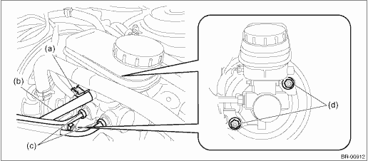
(1) Disconnect the fluid level gauge connector (a).
(2) Disconnect the clutch hose (b). (MT model)
(3) Disconnect the brake pipe (c).
(4) Remove the nut (d), and slowly remove the master cylinder assembly from the vacuum booster assembly.
 Assembly
BRAKE > Master CylinderASSEMBLYCAUTION:When replacing the reservoir tank, adhere the label to the position shown in the figure. (C5 model)Preparation items:C5 modelPart No.: Label (25080GA010)(a)La ...
 Disassembly
BRAKE > Master CylinderDISASSEMBLY1. Remove the reservoir tank.CAUTION:Be careful not to tighten a vise excessively.(1) Place the master cylinder assembly between aluminum plates and fix it on a vi ...
Other materials:
Removal
EXHAUST(H4DO) > Center Exhaust PipeREMOVALCAUTION:Vehicle components are extremely hot after driving. Be wary of receiving burns from heated parts.1. Turn the ignition switch to OFF.2. Lift up the vehicle.3. Remove the bolts, springs, and nuts securing the rear exhaust pipe to the center exhaust ...
Tripped sensor identification
The security indicator light flashes when
the alarm system has been triggered.
Also, the number of flashes indicates the
location of unauthorized intrusion or the
severity of impact on the vehicle.
When the ignition switch is turned to the
"ON" position, the indicator light will light
for ...
Wiper and washer
WARNING
In cold or freezing conditions, avoid using the windshield washer system of
the Subaru Ascent until the windshield has been properly warmed by the defroster.
If washer fluid is sprayed onto a cold surface, it may freeze instantly, reducing
visibility and creating a hazardous driving ...
