Subaru Crosstrek Service Manual: Removal
BRAKE > Brake Booster
REMOVAL
CAUTION:
• Do not allow brake fluid to come in contact with the painted surface of the vehicle body. If it does, wash off with water and wipe away completely.
• Before handling the airbag system components, always refer to “CAUTION” of “General Description” in “AIRBAG SYSTEM”. General Description > CAUTION">
1. Disconnect the ground cable from battery and wait for at least 60 seconds before starting work. NOTE">
2. Remove the column assembly - steering. Steering Column > REMOVAL">
3. Drain brake fluid from the reservoir tank completely.
4. Disconnect the air conditioner pipe. Hose and Pipe > REMOVAL">
5. Remove the power steering control module. Power Steering Control Module > REMOVAL">
6. Remove the master cylinder assembly. Master Cylinder > REMOVAL">
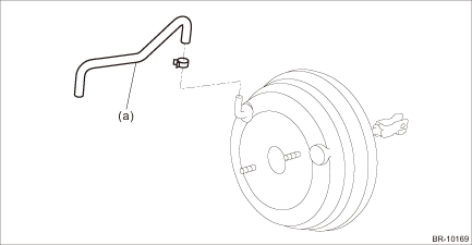
7. Remove the clamp and remove the vacuum hose (a).
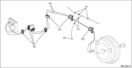
8. Remove the brake pipe assembly (a).
(1) Disconnect the starter connector (b) and harness clip (c).
(2) Remove the brake pipe assembly (a) from the pipe clip (d).
9. Remove the cover assembly - instrument panel LWR driver. Instrument Panel Lower Cover > REMOVAL">
10. Remove the knee airbag module. Knee Airbag Module > REMOVAL">
11. Remove the column assembly - steering. Steering Column > REMOVAL">
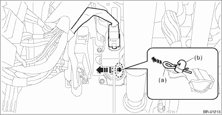
12. Remove the snap pin (a) and clevis pin (b), and remove the operating rod from the brake pedal.
CAUTION:
• Be careful not to apply excessive force to the operating rod when handling the operating rod. The angle may change by ±3°, and it may result in damage to power piston cylinder.
• Do not change the push rod length.
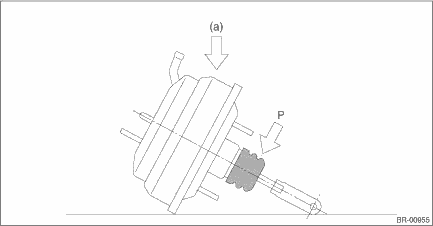
13. Remove the vacuum booster assembly.
CAUTION:
• Do not disassemble the vacuum booster assembly.
• Make sure that the booster shell and vacuum pipe are not subject to strong impacts.
• Be careful not to drop the vacuum booster assembly. If the vacuum booster assembly is dropped accidentally, replace it.
• Be careful when placing the vacuum booster assembly on floor.
• If external force (a) is applied from above when the vacuum booster assembly is placed in this position, the resin portion as indicated by “P” may become damaged.
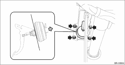
(1) Remove the nuts, and then remove the vacuum booster assembly.
 Inspection
BRAKE > Brake BoosterINSPECTION1. OPERATION CHECK WHEN NOT USING MEASURING DEVICESCAUTION:When checking operation, be sure to apply the parking brake securely.When an operation check is performed w ...
 Installation
BRAKE > Brake BoosterINSTALLATION1. Check and adjust the operating rod of the vacuum booster assembly.(1) Measure the length between the vacuum booster assembly mounting surface and clevis pin hole ...
Other materials:
Accessory power outlets
Power outlet below the climate control dials
Power outlet in the center console
Accessory power outlets are provided
below the climate control dials and in the
center console. Electrical power (12V DC)
from the battery is available at any of the
outlets when the ignition switch is in e ...
Dtc p0196 engine oil temperature sensor "a" range/performance
ENGINE (DIAGNOSTICS)(H4DO) > Diagnostic Procedure with Diagnostic Trouble Code (DTC)DTC P0196 ENGINE OIL TEMPERATURE SENSOR "A" RANGE/PERFORMANCEDTC DETECTING CONDITION:Detected when two consecutive driving cycles with fault occur.TROUBLE SYMPTOM:• Hard to start• Improper id ...
Dtc c1721 yaw rate sensor
VEHICLE DYNAMICS CONTROL (VDC) (DIAGNOSTICS) > Diagnostic Procedure with Diagnostic Trouble Code (DTC)DTC C1721 YAW RATE SENSORDTC DETECTING CONDITION:Defective yaw rate & G sensorTROUBLE SYMPTOM:• ABS does not operate.• VDC does not operate.• Hill start assist does not oper ...
