Subaru Crosstrek Service Manual: Procedure
HVAC SYSTEM (HEATER, VENTILATOR AND A/C) > Refrigerant Pressure with Manifold Gauge Set
PROCEDURE
1. REFRIGERANT GAS PRESSURE INSPECTION
1. Prepare the vehicle.
NOTE:
Check that the ambient temperature is 25 — 40°C (77 — 104°F) and that the humidity is 30% — 80%.
• Place the vehicle in the shade and windless condition, and open the front hood.
• Open the front windows and close all doors.
2. Check the refrigerant pressure.
Preparation tool:
Manifold gauge set
(1) Connect the manifold gauge set, and start the engine.
(2) Set the vehicle to the following conditions.
Item | Condition |
Engine | Warmed up (Engine coolant temperature indicator light: OFF) |
Air vent grille | Shutter is fully open. |
A/C switch | ON |
Temperature adjustment dial | LO (MAX COOL) |
FRESH/RECIRC switch | RECIRC |
Air flow control dial or switch | VENT |
Fan dial | Auto A/C model: 5/7 level |
Manual A/C model: 3/4 level |
(3) In the condition of step (2), idle the engine for 30 minutes.
(4) Read the gauge values on both high pressure side and low pressure side for manifold gauge.
3. Measure the air vent grille outlet opening temperature, ambient temperature and humidity.
Preparation tool:
Thermometer and hygrometer
NOTE:
For outlet opening temperature, measure the average temperature of center grille assembly and side grille assembly.
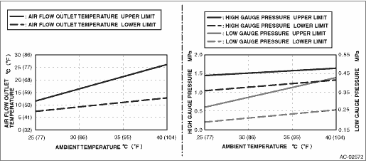
4. Check that the high and low pressures and outlet opening temperature for ambient temperature and humidity is within the standard value described in the chart below.
5. Refer to “DIAGNOSIS WITH SYMPTOM” if the inspection result is not within the standard value. Refrigerant Pressure with Manifold Gauge Set > INSPECTION">
 Inspection
HVAC SYSTEM (HEATER, VENTILATOR AND A/C) > Refrigerant Pressure with Manifold Gauge SetINSPECTION1. INSPECTION WITH PRESSURE SYMPTOMSSymptomsReferenceBoth high and low pressure sides are low. Refri ...
 Relay and fuse
...
Other materials:
Keyless access setting (models with "keyless access with pushbutton start
system")
Preparation for keyless access settings
1. Perform the preparation steps according
to "Preparation for car settings"
2. Operate the " " or "
" switch to
select the "Keyless Access Setting" item.
Then push the button.
Driver's door unlock setting
1. Perform the preparatio ...
Control screen and audio panel
Select to display the audio source
selection screen.
Select to display the play mode
currently selected. Refer to "Select
play mode"
Select to display iPod List. Refer to
"iPod settings"
Shows progress.
Turn to adjust volume.
Press to turn the audio system on/off.
Turn to ...
Dtc b1901 open in front p/t rh
AIRBAG SYSTEM (DIAGNOSTICS) > Diagnostic Chart with Trouble CodeDTC B1901 OPEN IN FRONT P/T RHDiagnosis start condition:Ignition voltage is 10 V to 16 V.DTC detecting condition:• Seat belt pretensioner (RH) circuit is open.• Pretensioner (RH) is faulty.• Pretensioner harness (RH ...
