
Subaru Crosstrek Owners Manual: Preparation for maintenance settings
1. Turn the ignition switch to the "ON" position.
2. Push and hold the button to show
the selection screen.
button to show
the selection screen.
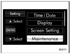
3. After the selection screen is displayed,
operate the " " or "
 " switch to show the
"Maintenance" item. Then, push the
" switch to show the
"Maintenance" item. Then, push the
 button.
 Maintenance settings
The items in the maintenance settings can
be set. To change the items, operate the
"
" or "
" switch. ...
 Engine oil setting
1. Perform the preparation steps according
to "Preparation for maintenance settings"
2. Operate the "
" or "
" switch to
select the "Engine Oil" item. Then push
the
but ...
Other materials:
Welcome lighting function (if
equipped)
The welcome lighting function turns on the
low beam headlight for smooth approaching
to or exiting from the vehicle at night or
in a dark place.
The function is activated while all of the
following conditions are met.
The light control switch is in the
"AUTO" position
It is dark enoug ...
Dtc c0072 abnormal yaw rate sensor output
VEHICLE DYNAMICS CONTROL (VDC) (DIAGNOSTICS) > Diagnostic Procedure with Diagnostic Trouble Code (DTC)DTC C0072 ABNORMAL YAW RATE SENSOR OUTPUTDTC DETECTING CONDITION:Defective yaw rate sensorTROUBLE SYMPTOM:• VDC does not operate.• EyeSight does not operate.STEPCHECKYESNO1.INTERVIEW ...
To hook the top tether
CAUTION
Except for the center seating
position, remove the head restraint
when mounting a child
restraint system. Otherwise, it
might be possible that the top
tether cannot be fastened tightly.
For the center seating position,
raise the center head restraint to
the extended posit ...
