
Subaru Crosstrek Owners Manual: Power door locking switches
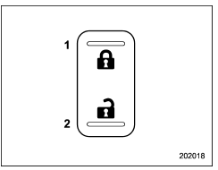
- Lock
- Unlock
All doors and the rear gate can be locked and unlocked by the power door locking switches located at the driver's side and the front passenger's side doors.
To lock the doors, push the front side of the switch.
To unlock the doors, push the rear side of the switch.
When you close the doors after you set the door locks, the doors remain locked.
NOTE
Make sure that you do not leave the key inside the vehicle before locking the doors from the outside using the power door locking switches.
Key lock-in prevention function
This function prevents the doors from being locked under the following conditions.
- The key is still in the ignition switch (models without "keyless access with push-button start system")
- The ignition switch is in the "ON" position (models with "keyless access with push-button start system")
This function's operational/non-operational setting can be changed by a SUBARU dealer. Contact a SUBARU dealer for details.
NOTE
- The factory setting (default setting) for this function is set as "operational".
- When leaving the vehicle, make sure you are holding the key before locking the doors.
Behavior with key lock-in prevention function operational
With the driver's door open, the doors are automatically kept unlocked even if the front side of the power door locking switch is pressed.
Behavior with key lock-in prevention function non-operational
- If the lock lever is turned to the front ("LOCK") position with the driver's door open and the driver's door is then closed with the lock lever in that position, the driver's door is locked.
- If the spare key is used to lock the driver's door from the outside of the vehicle, the door is locked.
 Battery drainage prevention function
If a door or the rear gate is not completely
closed, the interior lights will remain
illuminated as a result. However, several
lights are automatically turned off by the
battery drainage preventio ...
 Keyless access with push-button start system (if equipped)
The keyless access with push-button start
system allows you to perform the following
functions when you are carrying the
access key.
Locking and unlocking of the doors and
rear gate
Startin ...
Other materials:
Basic operation
Control switch
Up (select)
ENTER (push)
Down (select)
By operating "
" or "
" of the control
switch, the screens and selection items
can be switched. When the button is
pushed, the item can be selected and set. ...
Bottle holders
CAUTION
Do not pick up a bottle from the
bottle holder or put a bottle in the
holder while you are driving, as
this may distract you and lead to
an accident.
When placing a beverage in a
bottle holder, make sure it is
capped. Otherwise, the beverage
could spill when opening/closi ...
To temporarily cancel the cruise control
The cruise control can be temporarily
canceled in the following ways.
Press the "CANCEL" button.
Depress the brake pedal.
Depress the clutch pedal (MT models only).
WARNING
For CVT models, you can cancel the
cruise control by shifting the select
lever into the "N" position. Howeve ...
