Subaru Crosstrek Service Manual: Operation
VEHICLE DYNAMICS CONTROL (VDC) > VDC Sequence Control
OPERATION
1. While the VDC sequence control is performed, the operation of the hydraulic unit can be checked using the brake tester or pressure gauge after the hydraulic unit solenoid valve is operated.
2. VDC sequence control can be started by Subaru Select Monitor.
1. VDC SEQUENCE CONTROL WITH SUBARU SELECT MONITOR
NOTE:
In the event of any trouble, sequence control will not operate.
1. Connect the Subaru Select Monitor to data link connector.
NOTE:
For detailed operation procedures, refer to “Application help”.
(1) Turn the ignition switch to ON.
(2) On «Start» display, select «Diagnosis».
(3) On «Vehicle selection» display, input the target vehicle information and select «Confirmed».
(4) On «Main Menu» display, select «Each System».
(5) On «Select System» display, select «Brake Control System» and select «Enter».
(6) On «Select Function» display, select «Work Support».
(7) From the work support item list, select «VDC Function Check Mode».
2. Operate according to the procedures displayed in the Subaru Select Monitor.
3. The brake system being operated is displayed on the Subaru Select Monitor.
2. CONDITIONS FOR VDC SEQUENCE CONTROL
NOTE:
The control operation starts at point A.
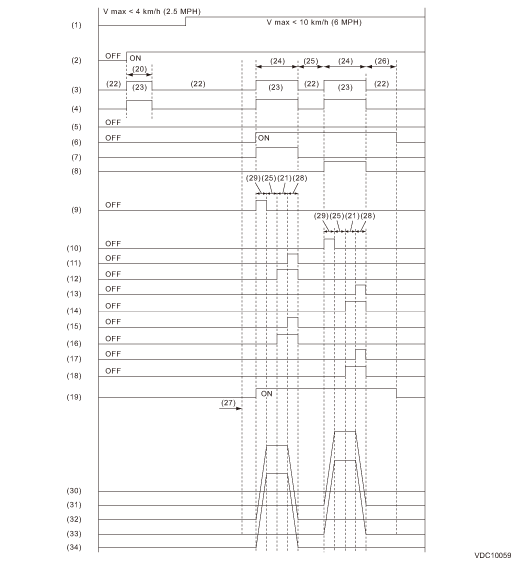
(1) | All wheel speed | (13) | FR decompression valve | (25) | 1 second |
(2) | Ignition key | (14) | FR compression valve | (26) | 1.6 seconds |
(3) | ABS warning light | (15) | RR decompression valve | (27) | Point A |
(4) | VDC warning light | (16) | RR compression valve | (28) | 0.4 seconds |
(5) | Switch - stop light | (17) | RL decompression valve | (29) | 0.8 seconds |
(6) | Valve relay | (18) | RL compression valve | (30) | Master cylinder pressure |
(7) | VDC switching valve 1 FL | (19) | Pump motor | (31) | FR wheel cylinder pressure |
(8) | VDC switching valve 1 FR | (20) | A few seconds | (32) | FL wheel cylinder pressure |
(9) | VDC switching valve 2 FL | (21) | 1.2 seconds | (33) | RL wheel cylinder pressure |
(10) | VDC switching valve 2 FR | (22) | Light OFF | (34) | RR wheel cylinder pressure |
(11) | FL decompression valve | (23) | Light ON | ||
(12) | FL compression valve | (24) | 3.4 seconds |

 Specification
VEHICLE DYNAMICS CONTROL (VDC) > VDC Sequence ControlSPECIFICATION1. CONDITIONS FOR COMPLETION OF VDC SEQUENCE CONTROLWhen the following conditions develop, the VDC sequence control stops and VDC o ...
Other materials:
Caution
BODY CONTROL SYSTEM (DIAGNOSTICS) > General DescriptionCAUTION1. SRS AIRBAG SYSTEMAirbag system wiring harness is routed near the body integrated unit and body control circuits.CAUTION:• Do not use the electrical test equipment on all airbag system wiring harnesses and connectors.• Be ...
Note
LIGHTING SYSTEM > Day Time Running Light SystemNOTEFor operation procedures of each component of the daytime running light system, refer to the respective section.• Headlight Assembly: Headlight Assembly">• Headlight bulb: Headlight Bulb">• Combination switch ( ...
Continuously variable transmission features
The continuously variable transmission is
electronically controlled and provides an
infinite number of forward speeds and 1
reverse speed. It also has a manual mode.
NOTE
When the engine coolant temperature
is still low, the transmission will
upshift or downshift at higher engine
speed ...
