Subaru Crosstrek Service Manual: Location
COMMUNICATION SYSTEM > Relay and Fuse
LOCATION
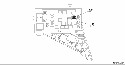
Main fuse box | Fuse 15 A (horn assembly) | (A) |
Horn relay | (B) |
NOTE:
For other related fuses, refer to the wiring diagram. Power Supply Circuit">
 Inspection
COMMUNICATION SYSTEM > Relay and FuseINSPECTION1. CHECK FUSE1. Remove the fuse and check visually.2. If the fuse is blown out, replace the fuse.2. CHECK RELAY1. Check the resistance between relay t ...

Other materials:
Welcome screen
When the door is unlocked and the
driver's door is opened, the welcome
screen will appear for a short time.
NOTE
The welcome screen will disappear
when the ignition switch is turned to
the "ON" position while the welcome
screen is displayed.
If any of the doors (including the
re ...
Windshield washer fluid
Windshield washer fluid warning light (type A)
Windshield washer fluid warning light (type B)
When there is only a small amount of
washer fluid remaining, the windshield
washer fluid warning light will illuminate.
When this occurs, refill the washer fluid. ...
Removal
EXHAUST(H4DO) > MufflerREMOVALCAUTION:Vehicle components are extremely hot after driving. Be wary of receiving burns from heated parts.1. Turn the ignition switch to OFF.2. Lift up the vehicle.3. Remove the bolts and self-locking nuts which secure the rear exhaust pipe to the muffler.4. Apply a c ...
