Subaru Crosstrek Service Manual: Installation
LUBRICATION(H4DO) > Oil Level Switch
INSTALLATION
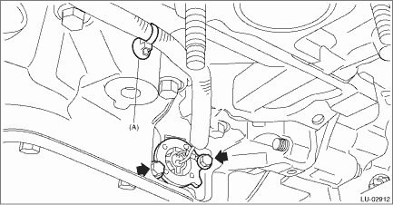
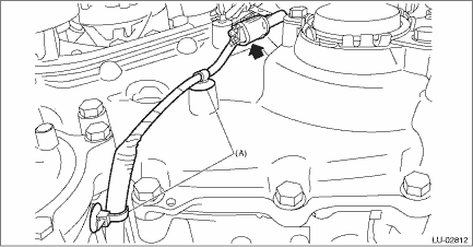
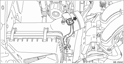
1. Install the oil level switch and the clip (A) to the oil pan upper.
NOTE:
• Use new O-rings.
• Apply a coat of engine oil to the O-rings.
Tightening torque:
6.4 N·m (0.7 kgf-m, 4.7 ft-lb)
2. Install the engine mounting LH onto the engine.
Tightening torque:
35 N·m (3.6 kgf-m, 25.8 ft-lb)
(A) | Front side | (B) | Rear side |
3. Lower the engine and remove the lifting device and wire ropes.

4. Remove the bolt and turn the transmission harness counterclockwise to install the transmission harness to the control valve body. (CVT model)
Tightening torque:
7 N·m (0.7 kgf-m, 5.2 ft-lb)

5. Install the bolt which holds the transmission harness stay. (CVT model)
Tightening torque:
7 N·m (0.7 kgf-m, 5.2 ft-lb)
6. Install the transmission case cover. (CVT model)
Tightening torque:
8 N·m (0.8 kgf-m, 5.9 ft-lb)

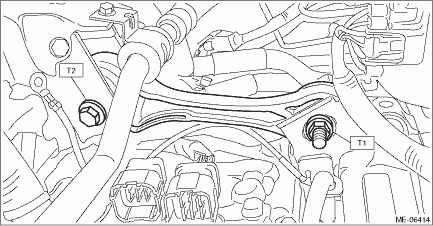
7. Install the pitching stopper.
Tightening torque:
T1: 50 N·m (5.1 kgf-m, 36.9 ft-lb)
T2: 58 N·m (5.9 kgf-m, 42.8 ft-lb)
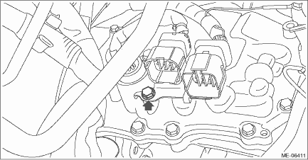
8. Connect the transmission radio ground terminal (C) to the vehicle body, and connect the bulkhead harness connector to the transmission harness connector (A) and the inhibitor harness connector (B). (CVT model)
Tightening torque:
13 N·m (1.3 kgf-m, 9.6 ft-lb)

9. Install the electric power steering gearbox. Electric Power Steering Gearbox > INSTALLATION">
10. Install the front drive shaft LH. Front Drive Shaft > INSTALLATION">
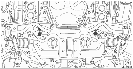
11. Install the nuts which hold the engine mounting to the front crossmember. (CVT model)
NOTE:
• Make sure that locators (A) of the engine mounting are securely inserted.
• Use a new nut.
Tightening torque:
60 N·m (6.1 kgf-m, 44.3 ft-lb)
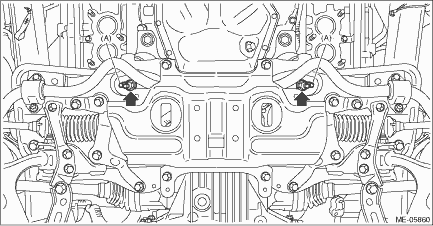
12. Install the nuts which hold the engine mounting to the front crossmember. (MT model)
NOTE:
Use a new nut.
Tightening torque:
60 N·m (6.1 kgf-m, 44.3 ft-lb)
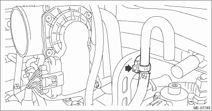
13. Connect the connector of oil level switch to the engine harness, and install the clip (A) securing the harness.
14. Install the front exhaust pipe. Front Exhaust Pipe > INSTALLATION">
15. Install the under cover.
16. Lower the vehicle.
17. Secure the air breather hose to the engine rear hanger using clip. (MT model)
18. Install the air intake case (rear).

19. Install the clip (A) which secures the air flow and intake air temperature sensor harness, and connect the connector to the air flow and intake air temperature sensor.
20. Install the air intake boot. Air Intake Boot > INSTALLATION">
21. Install the air intake duct. Air Intake Duct > INSTALLATION">
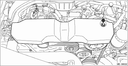
22. Install the V-belt cover.
Tightening torque:
7 N·m (0.7 kgf-m, 5.2 ft-lb)
23. Refill the engine oil. Engine Oil > REPLACEMENT">
24. Connect the battery ground terminal. NOTE">
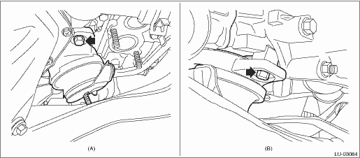
25. Change the front hood stay position from (B) to (A).
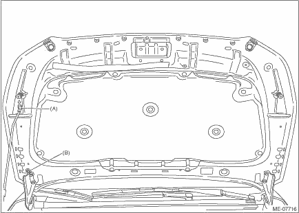
26. Install the front hood striker to the front hood by aligning the alignment marks (A), and close the front hood.
Tightening torque:
33 N·m (3.4 kgf-m, 24.3 ft-lb)

 Wiring diagram
LUBRICATION(H4DO) > Oil Level SwitchWIRING DIAGRAM• Engine electrical system Engine Electrical System > WIRING DIAGRAM">• CAN communication system CAN Communication System ...
 Removal
LUBRICATION(H4DO) > Oil Level SwitchREMOVAL1. Open the front hood, and make alignment marks (A) on the front hood striker and the front hood using a marker pen.2. Remove the front hood striker from ...
Other materials:
Map lights
Type A
Type B
To turn on the map light, push the switch.
To turn it off, push the switch again.
NOTE
For the type A map lights, although the
light switches are in the ON position,
the lights are automatically turned off
after approximately 30 seconds of
illumination to prevent the veh ...
Casual speech recognization
Due to natural language speech recognition
technology, this system enables recognition
of a command when spoken
naturally. However, the system cannot
recognize every variation of each command.
In some situations, it is possible to
omit the command for the procedure and
directly state the de ...
Removal
ENTERTAINMENT > Rear Accessory Power Supply SocketREMOVAL1. Disconnect the ground cable from battery and wait for at least 60 seconds before starting work. NOTE">2. Remove the console box assembly. Console Box > REMOVAL">3. Remove the socket assembly.(1) While releasing the c ...
