Subaru Crosstrek Service Manual: Installation
FUEL INJECTION (FUEL SYSTEMS)(H4DO) > Intake Manifold
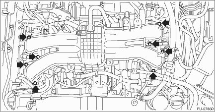
INSTALLATION
1. Install the engine wiring harness. Engine Wiring Harness > INSTALLATION">
2. Install the intake manifold to the tumble generator valve assembly.
NOTE:
Use a new gasket.
Tightening torque:
8.3 N·m (0.8 kgf-m, 6.1 ft-lb)
3. Connect the fuel delivery tube and evaporation hose.
(1) Connect the evaporation hose to fuel pipe assembly.
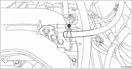
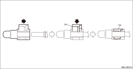
(2) Connect the quick connector of the fuel delivery tube to the fuel pipe assembly, and secure the fuel delivery tube using clip (A).
CAUTION:
• Check that there is no damage or dust on the quick connector. If necessary, clean the seal surface of the pipe.
• When connecting the quick connector, make sure to insert it all the way in before locking the slider.
• When it is difficult to lock the slider, check that the connector is fully inserted.
• After locking the slider, check again that the quick connector is securely connected.
NOTE:
Connect the quick connector as shown in the figure.
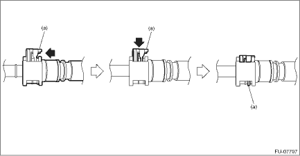
(a) | Slider |
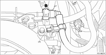
4. Connect the fuel delivery pipe to the fuel pipe LH.
CAUTION:
• Check that there is no damage or dust on the quick connector. If necessary, clean the seal surface of the pipe.
• When connecting the quick connector, make sure to insert it all the way in before locking the slider.
• When it is difficult to lock the slider, check that the connector is fully inserted.
• After locking the slider, check again that the quick connector is securely connected.
NOTE:
Connect the quick connector as shown in the figure.
(a) | Slider |
5. Install the intake manifold protector LH.
Tightening torque:
6.4 N·m (0.7 kgf-m, 4.7 ft-lb)
6. Connect the fuel delivery pipe to the fuel pipe RH.
CAUTION:
• Check that there is no damage or dust on the quick connector. If necessary, clean the seal surface of the pipe.
• When connecting the quick connector, make sure to insert it all the way in before locking the slider.
• When it is difficult to lock the slider, check that the connector is fully inserted.
• After locking the slider, check again that the quick connector is securely connected.
NOTE:
Connect the quick connector as shown in the figure.
(a) | Slider |

7. Install the intake manifold protector RH.
Tightening torque:
6.4 N·m (0.7 kgf-m, 4.7 ft-lb)

8. Install the air cleaner case (rear) together with the air cleaner element. Air Cleaner Case > INSTALLATION">
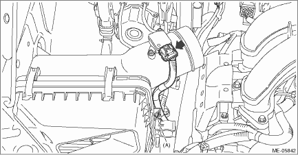
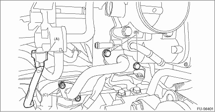
9. Secure the bulkhead wiring harness with clip (A) and connect the connector to the mass air flow and intake air temperature sensor.
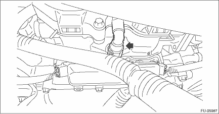
10. Connect the brake booster vacuum hose to the intake manifold.

11. Connect the PCV hose (A) to intake manifold.
12. Connect the connector (B) to the manifold absolute pressure sensor.
13. Connect the connector (C) to the throttle position sensor.

14. Connect the connector (A) to the purge control solenoid valve.
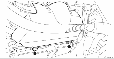
15. Tighten the nut (C) and bolt (B) which hold EGR pipe to the water pipe assembly.
NOTE:
• Use a new gasket.
• Always tighten the EGR pipe at (C) first, and then (B).
Tightening torque:
6.4 N·m (0.7 kgf-m, 4.7 ft-lb)
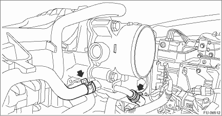
16. Install the preheater hose to the throttle body.
17. Install the air intake boot. Air Intake Boot > INSTALLATION">
18. Lift up the vehicle.
19. Install the under cover. Front Under Cover > INSTALLATION">
20. Lower the vehicle.
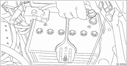
21. Connect the battery ground terminal.
22. Fill engine coolant. Engine Coolant > REPLACEMENT">
 Inspection
FUEL INJECTION (FUEL SYSTEMS)(H4DO) > Intake ManifoldINSPECTION1. Check that the intake manifold and fuel pipe have no deformation, cracks and other damages.2. Check that the hose has no cracks, da ...
 Knock sensor
...
Other materials:
Removal
BRAKE > Master CylinderREMOVALCAUTION:• Do not allow brake fluid to come in contact with the painted surface of the vehicle body. If it does, wash off with water and wipe away completely.• Prepare a container to catch grease or oil, etc. If any grease or oil spills, wipe it off and cl ...
Removal
DRIVE SHAFT SYSTEM > Front Hub Unit BearingREMOVAL1. Lift up the vehicle, and then remove the front wheels.2. Remove the axle nut.CAUTION:Do not loosen the axle nut while the front axle is loaded. Doing so may damage the hub unit bearing.(1) Lift the crimped section of axle nut.(2) Remove the axl ...
Note
LIGHTING SYSTEM > Front Fog Light SystemNOTEFor operation procedures of each component of the front fog light system, refer to the respective section.• Combination switch (light): Combination Switch (Light)">• Front fog light assembly: Front Fog Light Assembly">&bull ...
