Subaru Crosstrek Service Manual: Installation
FUEL INJECTION (FUEL SYSTEMS)(H4DO) > Engine Wiring Harness
INSTALLATION
1. Route the engine wiring harness around the engine and connect connectors.
• Structural diagram 1
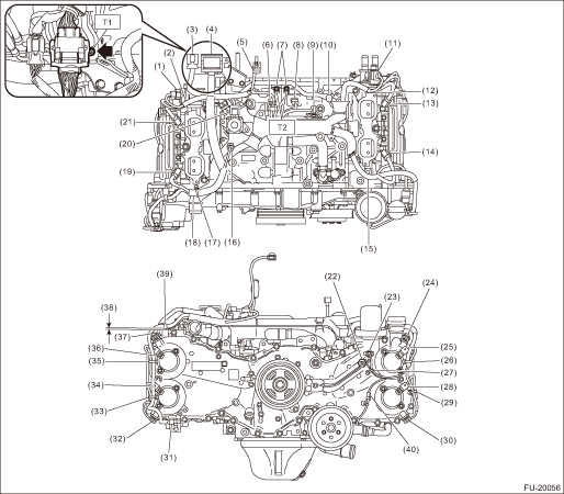
(1) | Tumble generator valve actuator RH | |
(2) | Be careful of pinching when installing the intake manifold. | |
(3) | Engine harness connector (16P) | |
(4) | Engine harness connector (54P) | |
(5) | Throttle position sensor connector | |
(6) | Manifold absolute pressure sensor connector | |
(7) | Engine ground (2 locations) | |
(8) | Crankshaft position sensor | |
(9) | Knock sensor | |
(10) | Purge control solenoid valve connector | |
(11) | Tumble generator valve actuator LH | |
(12) | Be careful of pinching when installing the intake manifold. | |
(13) | Fuel injector (#4) | |
(14) | Fuel injector (#2) | |
(15) | Be careful of pinching when installing the intake manifold and A/C bracket. | |
(16) | Engine coolant temperature sensor | |
(17) | Secure the clip to the screw hole. | |
(18) | Be careful of pinching when installing the intake manifold. | |
(19) | Fuel injector (#1) | |
(20) | EGR valve | |
(21) | Fuel injector (#3) | |
(22) | Oil pressure switch | |
(23) | Engine oil temperature sensor | |
(24) | Intake camshaft position sensor LH | |
(25) | Intake oil control solenoid LH | |
(26) | Secure the clip to the screw hole. | |
(27) | Secure the clip to the screw hole. | |
(28) | Exhaust oil control solenoid LH | |
(29) | Secure the clip to the screw hole. | |
(30) | Exhaust camshaft position sensor LH | |
(31) | Secure the clip to the oval hole. | |
(32) | Exhaust camshaft position sensor RH | |
(33) | Secure the clip to the screw hole. | |
(34) | Exhaust oil control solenoid RH | |
(35) | Secure the clip to the screw hole. | |
(36) | Intake oil control solenoid RH | |
(37) | Intake camshaft position sensor RH | |
(38) | Maximum of 0 — 2 mm (0 — 0.079 in) gap is allowed. | |
(39) | Secure the clip to the screw hole. | |
(40) | Oil level switch connector | |
Tightening torque: N·m (kgf-m, ft-lb) | ||
T1: | 7.5 (0.8, 5.5) | |
T2: | 19 (1.9, 14.0) | |
• Structural diagram 2

(1) | Secure the clip to the screw hole. | |
(2) | Ignition coil No. 4 | |
(3) | Ignition coil No. 2 | |
(4) | Secure the clip to the screw hole. | |
(5) | Ignition coil No. 3 | |
(6) | Ignition coil No. 1 | |
(7) | Front oxygen (A/F) sensor | |
(8) | Rear oxygen sensor | |
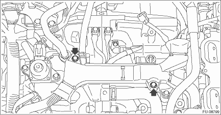
2. Install the engine wiring harness.
Tightening torque:
6.4 N·m (0.7 kgf-m, 4.7 ft-lb)
3. Install the intake manifold. Intake Manifold > INSTALLATION">
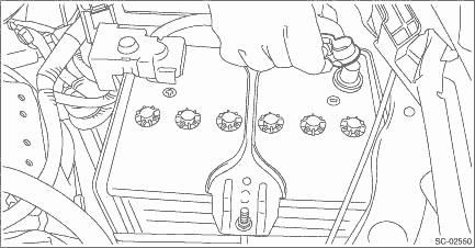
4. Connect the battery ground terminal.
 Removal
FUEL INJECTION (FUEL SYSTEMS)(H4DO) > Engine Wiring HarnessREMOVAL1. Release the fuel pressure. Fuel > PROCEDURE">2. Disconnect the ground cable from battery.3. Remove the intake manifo ...

Other materials:
Removal
EMISSION CONTROL (AUX. EMISSION CONTROL DEVICES)(H4DO) > EGR CoolerREMOVAL1. Disconnect the ground cable from battery.2. Drain engine coolant. Engine Coolant > REPLACEMENT">3. Remove the center exhaust pipe. Center Exhaust Pipe > REMOVAL">4. Lower the vehicle.5. Remove the ...
Electrical component location Location
POWER ASSISTED SYSTEM (POWER STEERING) (DIAGNOSTICS) > Electrical Component LocationLOCATION(1)Steering gearbox(3)STEERING warning light(5)VDCCM&H/U(2)Power steering control module(4)Engine control module (ECM)(6)Data link connector (for Subaru Select Monitor)• U5 and U6 models• C ...
Removal
CONTINUOUSLY VARIABLE TRANSMISSION(TR580) > Transfer ClutchREMOVAL1. Remove the transmission assembly from the vehicle. Automatic Transmission Assembly > REMOVAL">2. Remove the extension case. Extension Case > REMOVAL">3. Remove the transfer clutch assembly.4. Remove the t ...
