Subaru Crosstrek Service Manual: Installation
FRONT SUSPENSION > Front Crossmember
INSTALLATION
1. Check the crossmember for damage or cracks, and correct or replace if defective.
2. Install the universal joint assembly - steering. Universal Joint > INSTALLATION">
3. Install each part in the reverse order of removal.
CAUTION:
• Use a new bolt and self-locking nut. For parts which are not reusable, refer to “COMPONENT”. General Description > COMPONENT">
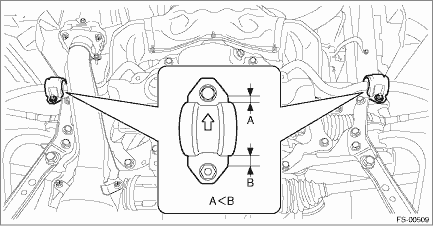
• Always tighten the bushing in the state where the vehicle is at curb weight and the wheels are in full contact with the ground.
• Install the clamp - stabilizer bushing with the arrow mark facing the front of the vehicle.
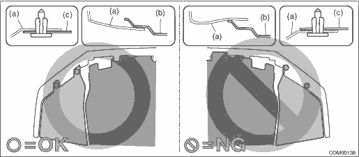
• Install so that the front end of the under cover (b) comes inside the bumper face - front (a), and the front end of the mud guard (c) comes outside the bumper face - front (a).
Tightening torque:
Engine mounting to Front crossmember assembly: General Description > COMPONENT">
Universal joint assembly - steering: 24 N·m (2.45 kgf-m, 17.7 ft-lb)
V-belt cover: 7.5 N·m (0.76 kgf-m, 5.5 ft-lb)
Under cover - front: 18 N·m (1.84 kgf-m, 13.3 ft-lb)
Front suspension parts: General Description > COMPONENT">
When tightening the castle nut, tighten the castle nut to the specified torque first, then tighten it further but within 60° until the hole in the ball stud is aligned with a slot in castle nut.
4. Install the front wheels.
Tightening torque:
Except for C4 model: 120 N·m (12.24 kgf-m, 88.5 ft-lb)
C4 model: 100 N·m (10.20 kgf-m, 73.8 ft-lb)
5. Inspect the wheel alignment and adjust if necessary.
• Inspection: Wheel Alignment > INSPECTION">
• Adjustment: Wheel Alignment > ADJUSTMENT">
CAUTION:
If the steering wheel and steering angle sensor are removed, perform the following VDC setting mode.
– Model without EyeSight: VDC sensor midpoint setting mode VDC Control Module and Hydraulic Control Unit (VDCCM&H/U) > ADJUSTMENT">
– Model with EyeSight: Neutral of Steering Angle Sensor & Lateral G Sensor 0 point setting VDC Control Module and Hydraulic Control Unit (VDCCM&H/U) > ADJUSTMENT">
– Model with EyeSight: Longitudinal G sensor & lateral G sensor 0 point setting VDC Control Module and Hydraulic Control Unit (VDCCM&H/U) > ADJUSTMENT">
6. Perform reinitialization of the auto headlight beam leveler system. (Model with auto headlight beam leveler) Auto Headlight Beam Leveler System > PROCEDURE">

 Removal
FRONT SUSPENSION > Front CrossmemberREMOVALCAUTION:• The power steering control module continues to operate after the engine stops and calculate the temperature in the control module. Therefo ...
Other materials:
Inspection
WIPER AND WASHER SYSTEMS > Washer Tank and MotorINSPECTION1. WASHER PUMPApply battery voltage to the connector terminal of the motor pump assembly - washer, and make sure that the motor operates.2. WASHER FLUID LEVEL SENSOR1. Check the connection status of washer fluid level sensor connector.2. D ...
Engine oil pressure Inspection
MECHANICAL(H4DO) > Engine Oil PressureINSPECTION1. Disconnect the ground cable from battery. NOTE">2. Remove the oil pressure switch. Oil Pressure Switch > REMOVAL">3. Install the oil pressure gauge to the chain cover.4. Connect the battery ground terminal. NOTE">5. ...
Preparation tool
IMMOBILIZER (DIAGNOSTICS) > General DescriptionPREPARATION TOOL1. SPECIAL TOOLILLUSTRATIONTOOL NUMBERDESCRIPTIONREMARKS — SUBARU SELECT MONITOR 4Used for setting of each function and troubleshooting for electrical system.NOTE:For detailed operation procedures of Subaru Select Monitor 4, refer t ...
