Subaru Crosstrek Service Manual: Installation
EMISSION CONTROL (AUX. EMISSION CONTROL DEVICES)(H4DO) > Leak Check Valve Assembly
INSTALLATION
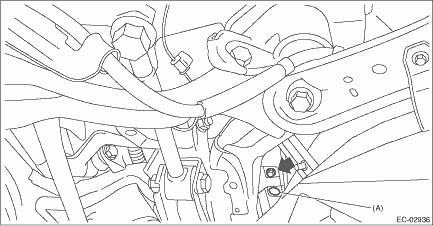
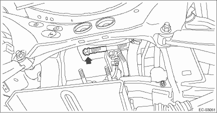
1. Install the leak check valve assembly to the vehicle with the bolt and clip (A).
Tightening torque:
7.5 N·m (0.8 kgf-m, 5.5 ft-lb)
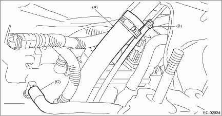
2. Connect the connector to the leak check valve assembly.
3. Connect the intake hose (C) to the connector.
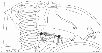
4. Securely insert the fuel filler hose (A) and evaporation hose (B) until the hose end contacts the spool, then attach the clamp and clip as shown in the figure.
Tightening torque:
2.5 N·m (0.3 kgf-m, 1.8 ft-lb)
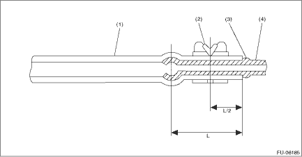
(1) | Hose | (3) | Spool | (4) | Pipe |
(2) | Clamp and clip |
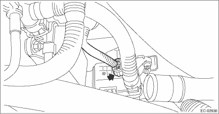
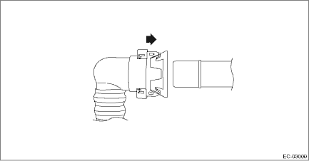
5. Connect the drain tube to the canister.
NOTE:
Connect the quick connector as shown in the figure.
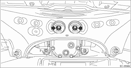
6. Lift up the transmission jack gradually, and set the rear differential to the rear sub frame assembly.
NOTE:
When inserting the stud bolt into the bushing portion of the rear sub frame assembly, adjust the angle and location of transmission jack and jack stand.
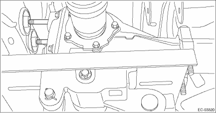
7. Temporarily tighten the self-locking nuts which hold the rear differential to the rear sub frame assembly.
NOTE:
Use a new self-locking nut.
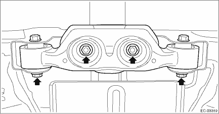
8. Set the rear differential member to the rear sub frame assembly and rear differential, and temporarily tighten the self-lock nuts which secure the rear differential member to the rear sub frame assembly and rear differential.
NOTE:
Use a new self-locking nut.
9. Remove the transmission jack from the rear differential.
10. Tighten the self-locking nuts which secure the rear differential member to the rear sub frame assembly and rear differential.
Tightening torque:
T1: 50 N·m (5.1 kgf-m, 36.9 ft-lb)
T2: 110 N·m (11.2 kgf-m, 81.1 ft-lb)
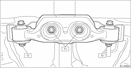
11. Tighten the self-locking nuts which secure the rear differential to the rear sub frame assembly.
Tightening torque:
70 N·m (7.1 kgf-m, 51.6 ft-lb)
12. Install the propeller shaft. Propeller Shaft > INSTALLATION">
13. Install the rear exhaust pipe. Rear Exhaust Pipe > INSTALLATION">
14. Lower the vehicle.
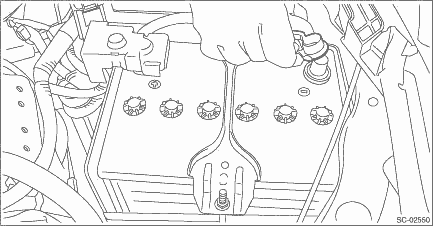
15. Connect the battery ground terminal.
 Inspection
EMISSION CONTROL (AUX. EMISSION CONTROL DEVICES)(H4DO) > Leak Check Valve AssemblyINSPECTION1. CHECK SWITCHING VALVE1. Check the resistance between switching valve terminals.Terminal No.Standard1 a ...
 Pcv hose
...
Other materials:
Inspection
FUEL INJECTION (FUEL SYSTEMS)(H4DO) > Crankshaft Position SensorINSPECTION1. CRANKSHAFT POSITION SENSOR (METHOD WITH OSCILLOSCOPE)1. Prepare an oscilloscope.2. Remove the glove box. Glove Box > REMOVAL">3. Connect the probe to ECM connector.Terminal No.Probe16+1−4. Start the eng ...
Disposal of pretensioner Procedure
SEAT BELT SYSTEM > Disposal of PretensionerPROCEDUREWARNING:Make sure to follow the instructions below. Otherwise, personal injuries may occur.• Before discarding a pretensioner, always perform an activation process to prevent any false activation.• Wear protective gloves, safety gogg ...
Dtc c1251 wheel speed sensor system
VEHICLE DYNAMICS CONTROL (VDC) (DIAGNOSTICS) > Diagnostic Procedure with Diagnostic Trouble Code (DTC)DTC C1251 WHEEL SPEED SENSOR SYSTEMNOTE:For the diagnostic procedure, refer to “DTC C1241 REAR LEFT ABS SENSOR CIRCUIT”. Diagnostic Procedure with Diagnostic Trouble Code (DTC) > ...
