Subaru Crosstrek Service Manual: Installation
DRIVE SHAFT SYSTEM > Rear Drive Shaft
INSTALLATION
1. Replace the rear differential side oil seal. Rear Differential Side Oil Seal > REPLACEMENT">
NOTE:
After pulling out the drive shaft assembly, be sure to replace with a new oil seal.
2. Insert the drive shaft assembly into the rear hub spline, and pull it into the specified position.
CAUTION:
• Be careful not to damage the magnetic encoder.
• Do not get closer the tool which charged magnetism to magnetic encoder.
• Do not hammer the drive shaft assembly when installing.
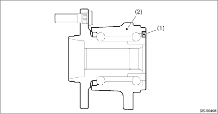
(1) | Magnetic encoder | (2) | Rear hub unit bearing |
3. Tighten the axle nut temporarily.
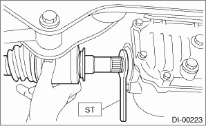
4. Using the ST, install the rear drive shaft assembly to the rear differential.
Preparation tool:
ST: OIL SEAL PROTECTOR (28099PA090)
5. Install the rear differential assembly to the rear sub frame assembly.
CAUTION:
Be sure to use a new self-locking nut.
Tightening torque:
Differential assembly — bushing - differential: 70 N·m (7.1 kgf-m, 51.6 ft-lb)
Differential assembly — rear sub frame assembly: 110 N·m (11.2 kgf-m, 81.1 ft-lb)
6. Install the sensor assembly - headlight beam leveler.
Tightening torque:
7.5 N·m (0.8 kgf-m, 5.5 ft-lb)
7. While pressing the brake pedal, tighten the new axle nuts to the specified torque.
CAUTION:
Do not load the rear axle before tightening the axle nut. Doing so may damage the hub unit bearing.
Tightening torque:
190 N·m (19.4 kgf-m, 140.1 ft-lb)
8. Lock the axle nut securely.

9. Fill differential gear oil.
10. Install the rear wheels.
Tightening torque:
Except for C4 model: 120 N·m (12.2 kgf-m, 88.5 ft-lb)
C4 model: 100 N·m (10.2 kgf-m, 73.8 ft-lb)
11. Perform reinitialization of the auto headlight beam leveler system. (Model with auto headlight beam leveler) Auto Headlight Beam Leveler System > PROCEDURE">
 Inspection
DRIVE SHAFT SYSTEM > Rear Drive ShaftINSPECTIONCheck the removed parts for damage, wear, corrosion etc. Repair or replace if defective.• DOJ (Double Offset Joint):Check for seizure, corrosion ...

Other materials:
Adjustment
WIPER AND WASHER SYSTEMS > Front Washer Nozzle and HoseADJUSTMENT1. NOZZLE - WINDSHIELD WASHER1. Turn the wiper switch to OFF position.2. While the vehicle is at a standstill, insert a precision screwdriver (A) or equivalent wrapped with protective tape into the clearance on the upper/lower side ...
Installation
EMISSION CONTROL (AUX. EMISSION CONTROL DEVICES)(H4DO) > EGR Control ValveINSTALLATIONInstall in the reverse order of removal.NOTE:Use new O-rings and gaskets.Tightening torque:22 N·m (2.2 kgf-m, 16.2 ft-lb)Tightening torque:3 N·m (0.3 kgf-m, 2.2 ft-lb) ...
Air filtration system
Your vehicle's air conditioning system is
equipped with an air filtration system.
Replace the air filter element according
to the replacement schedule found in the
"Warranty and Maintenance Booklet". This
schedule should be followed to maintain
the filter's dust collection ability. Under
ex ...
