Subaru Crosstrek Service Manual: Installation
DRIVE SHAFT SYSTEM > Propeller Shaft
INSTALLATION
1. Before installation, check the following items, and replace the propeller shaft assembly as necessary.
• Dents or cracks on the tube surface
• Splines for deformation or abnormal wear
• Unsmooth joint operation or abnormal noise
• Center bearing for free play, noise or non-smooth operation.
• Oil seals for abnormal wear or damage
• Damaged center bearing
2. Apply fluid or gear oil to the oil seal lip and the propeller shaft.
• CVT model: SUBARU CVT OIL FOR LINEARTRONIC
• MT model: GL-5
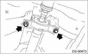
3. Insert the sleeve yoke into the transmission and attach center bearing to body.
Tightening torque:
52 N·m (5.3 kgf-m, 38.4 ft-lb)
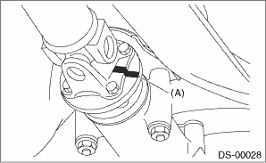
4. Align the alignment marks (A), and connect the yoke flange and rear differential.
Tightening torque:
31 N·m (3.2 kgf-m, 22.9 ft-lb)
5. Check the propeller shaft with the propeller shaft installed to the vehicle. Propeller Shaft > INSPECTION">
6. Install the center exhaust cover.
Tightening torque:
18 N·m (1.8 kgf-m, 13.3 ft-lb)
7. Install the center exhaust pipe, rear exhaust pipe and muffler.
• Center exhaust pipe & rear exhaust pipe: Rear Exhaust Pipe > INSTALLATION">
• Muffler: Muffler > INSTALLATION">
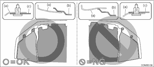
8. Install the under cover - front.
CAUTION:
Install so that the front end of the under cover (b) comes inside the bumper face - front (a), and the front end of the mud guard (c) comes outside the bumper face - front (a).
Tightening torque:
18 N·m (1.84 kgf-m, 13.3 ft-lb)
9. Lower the vehicle.
 Removal
DRIVE SHAFT SYSTEM > Propeller ShaftREMOVALCAUTION:• Before removing propeller shaft, wrap metal parts with a cloth or rubber material.• Do not disassemble the center EDJ of the propell ...
 Rear axle
...
Other materials:
At oil temp warning light (CVT models)
If this light illuminates when the engine is
running, it may indicate that the transmission
fluid temperature is too hot.
If the light illuminates while driving, immediately
stop the vehicle in a safe place
and let the engine idle until the warning
light turns off.
Transmission control ...
Removal
FUEL INJECTION (FUEL SYSTEMS)(H4DO) > Fuel InjectorREMOVAL1. Release the fuel pressure. Fuel > PROCEDURE">2. Disconnect the ground cable from battery.3. Open the fuel filler lid and remove the fuel filler cap.NOTE:This operation is required to release the inner pressure of the fuel ta ...
Note
GLASS/WINDOWS/MIRRORS > Remote Control Mirror SystemNOTEFor procedure of each component in the remote control mirror system, refer to the respective section.• Outer mirror assembly: Outer Mirror Assembly">• Remote control mirror switch: Remote Control Mirror Switch"> ...
